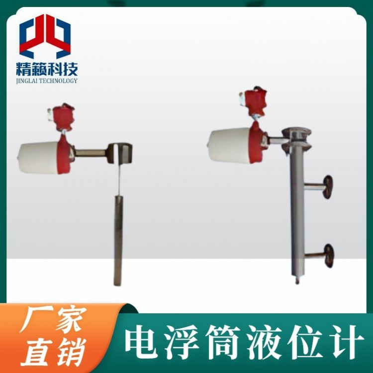
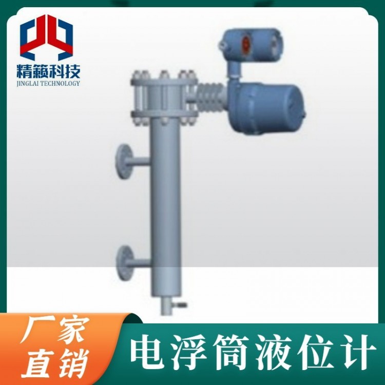
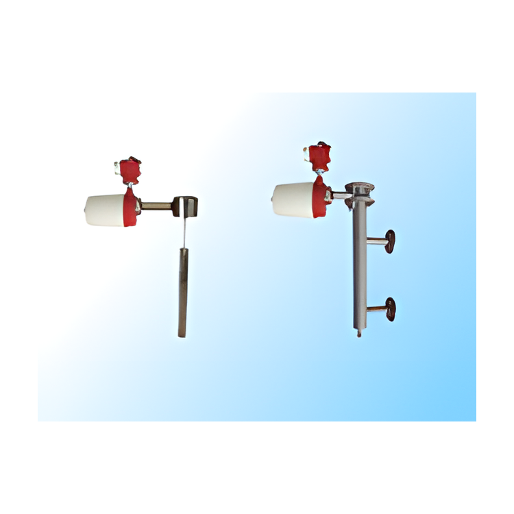


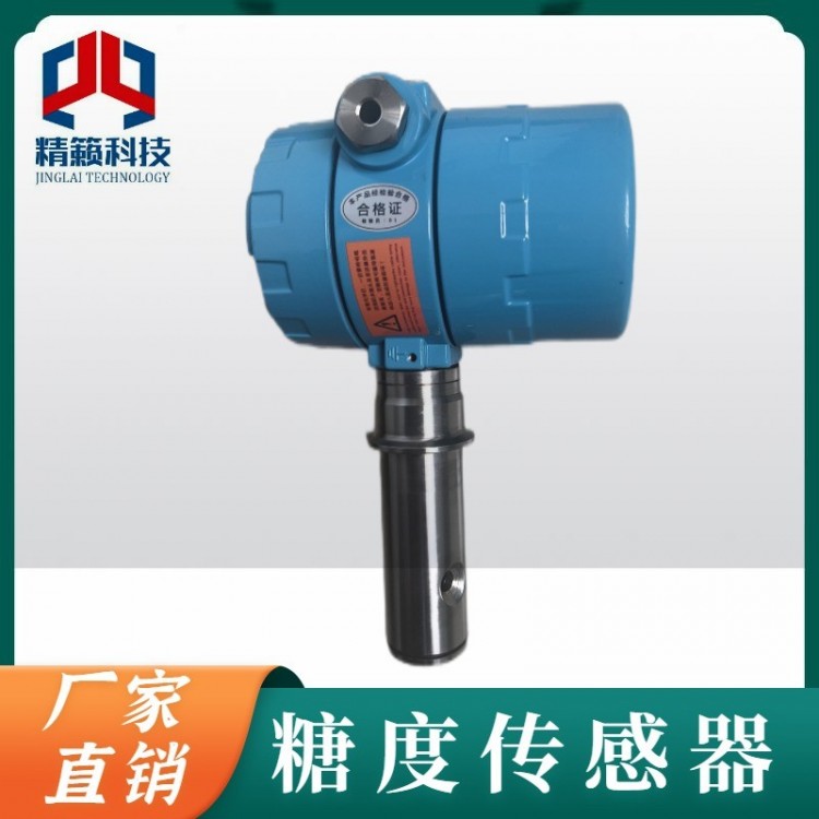
Structural Principles
The LC3010 series is composed of the original DLC3000 intelligent liquid level controller, float measuring chamber, measuring mechanism, float, torsion tube, and more. The float is submerged in the liquid within the measuring chamber and rigidly connected to the torsion tube system. The force the torsion tube system withstands is the net weight of the float minus the buoyant force exerted on it by the liquid. This resultant force twists the torsion tube to a certain angle. Changes in the position, density, or interface level of the measured liquid cause the float position to change, which is transmitted to the torsion tube component, causing it to rotate. The rotational motion of the torsion tube is transferred to the lever of the intelligent liquid level controller, causing a displacement of the magnet fixed on the lever component, altering the magnetic field detected by the Hall effect sensor and converting it into an electrical signal. The transmitter uses a microcontroller and related electronic circuits to measure process variables, providing a 4-20mA current signal output in a two-wire system, and driving an LCD display as well as providing HART communication capabilities. The microcontroller within the transmitter not only has environmental temperature compensation and linearization processing functions but also compensates for changes in liquid density caused by process temperature variations.
Features
Process Temperature: -196°C to +400°C
Pressure Grades: PN 1.6, 4.0, 6.3, 10, 16, 25, 32 MPa
Indicator: 5-digit configurable to %mA or other physical units
Signal noise is suppressed using Smart filtering.
The measurement signal can be linearized or customized according to user requirements.
Use the machine's buttons for routine operations.
Utilize HART or FOXCOM communication protocols for communication
Supports Fieldbus FF communication protocol
Simulated output signals for loop testing
Continuous self-diagnosis
Configurable safety setpoints
Materials for various corrosive media are available for selection.
Shell protection IP66 (per DIN 40050)
The product features explosion-proof and intrinsically safe properties, suitable for use in hazardous areas.
Sensors and amplifiers are available for either integrated or separate installation.
Key Technical Parameters
Measurement Range: 300~3,000mm (larger range available upon request)
Accuracy: Liquid level measurement ±0.5% FS, boundary measurement ±1% FS
Repeatability: ≤±0.25% FS
Dead Zone: ≤±0.2% FS
Power Supply: 12~30VDC
Output Signal: Analog: 4-20mA DC
Digital Quantity: By HART or FOXCOM communication protocol, Fieldbus FF communication protocol
LCD Display: Analog mA or Level, Boundary, and Percentage Range
Load Resistance: 700Ω (when powered by 24VDC)
Density Range: 100 < ρ < 2000 kg/m³
Density difference: 0.05 g/cm³
Working Pressure: 2.5~32.0 MPa
Medium Temperature: -196°C to +400°C
Ambient Temperature: -40 to +70℃
Impact of working conditions:
Power Supply Impact: Output variation ≤ ±0.2% FS when voltage varies between the minimum and maximum specified values.
Temperature Influence: ≤0.1% / 10℃
Alarm Current: The transmitter outputs an alarm current when the liquid level is 10% below the transmitter's lower range limit or 10% above the upper range limit. The alarm current is set to either 3.8mA or 22.8mA according to the configuration.
Protection Rating: IP65 (NEMA 4X)
Intrinsically Safe: Type Exia II CT1~T4
Airtight Type: ExdIICT1~T6
Electrical Interface: 2 x 1/2-14 NPT Female Threads
Cable Diameter: 6-12mm
Process Connection:
Buoyant筒式:Features DIN or ANSI flange standards, flange bore DN80 or above 3", smaller flange sizes please inquire at time of order
Floating Sphere Type: HG20592~20635-97, Flanges with DN20 and above; other flange standards (such as GB, JB/T, HGJ, ANSI, DIN, etc.) please specify upon order.
Hot jacket: DN15 PN1.0 RF, other specifications please specify when ordering.
Amplifier Split Mount Installation Accessories: Installation Components
Cable Length: 3m / 10m / Customer-Specified Length
Material: Buoy: 304; 316
Clamping body: Carbon steel; 304; 316; Haste C alloy
Clamping Body Heat Shroud: 304
External Buoyancy Cylinder: Carbon Steel; 304; 316
Torque Tube: 316L; IncoNel 600, 3J1, 3J53, Haste C alloy
Connector Box: Aluminum Alloy
Design Selection:
Registered Model | LC3010 Smart Buoy Level Transmitter |
Communication Methods | Default HART Communication Protocol |
Main Material | 304 |
Q235 steel | |
321 SCS321 1Cr18Ni9Ti 1.4873 | |
316Ti OCr18Ni12Mo2Ti 1.4571 | |
316 SVS316 OOCr17Ni12Mo2 1.4401 | |
316L SVS316L OOCr14Ni12Mo2 1.4435 | |
Special Material (Please Specify) | |
Installation Method | Side-mounted floating buoy |
Side-bottom mounted external buoyant buoy | |
Top-side mounted floating buoy | |
Floating Sphere Top and Bottom Installation Type | |
Internal Buoyant筒顶mounted | |
Parameter under Test | Measure Liquid Level |
Measurement Interface | |
Measure Density | |
Pressure Grade | 2.5MPa/Class 150LB ANSI |
4.0MPa/Class 300LB ANSI | |
6.3MPa/Class 600LB ANSI | |
16.0MPa/Class 900LB ANSI | |
32.0MPa/Class 1500LB ANSI | |
40.0MPa/Class 2500LB ANSI | |
Process Temperature | Room Temperature -40℃ to 150℃ |
High Temperature Type - 150℃ to 400℃ | |
Low-temperature type - from -196℃ to 150℃ | |
Explosion-proof type | No explosion-proof requirements |
Explosion-proof ExdIICT1-T6 | |
intrinsic safety ExiaIICT1~T6 | |
Safety barrier (see instruction manual) | |
Additional Steam Jacket | Tubular body without jacket |
Steam jacket, process connection | |
Steam jacket / Process connection / JB/T82.1-94 DN15 PN1.0 | |
Measuring Range (MM) | 0~1200mm |
Medium density kg/m³ | 998 |