


I. Application and Performance
1. Usage:
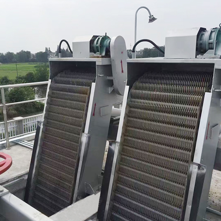
The woven wire mesh格栅 is primarily used to intercept smaller weeds and debris in water flow. It is widely applicable in direct and secondary circulation water supply systems of thermal power plants, as well as in water intake projects for metallurgy, chemical industry, oil, urban wastewater treatment, and tap water departments.
2. Performance:
Wired mesh gratings are fine filtration and cleaning equipment for water treatment, featuring easy dirt removal, reliable filtration, smooth water flow, and high efficiency. Moreover, they have a long service life, low power consumption, minimal noise, stable operation, and easy maintenance, with a small footprint. Suitable for various water qualities such as seawater and freshwater. When paired with level difference detection and control devices, they can achieve automated operation.
3. Terms of Use:
The mesh opening size of the net is relatively small. To ensure the normal operation of the grate, a coarse debris rack with a mesh opening size gap not exceeding 50 millimeters should be installed in front of the grate. Depending on the characteristics of the water source, if there is a significant accumulation of ice, silt, and other sediments, additional preventive facilities should be added in front of the intake. During the operation of the grate, the required flushing water volume in the slag washing channel is approximately 3.5 tons/hour, which is sufficient for 1 to 4 grates. Moreover, the flushing water pressure should not be less than 0.2 MPa.
Series Models and Main Technical Parameters:
1. Model Description:
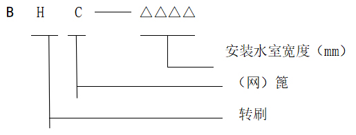
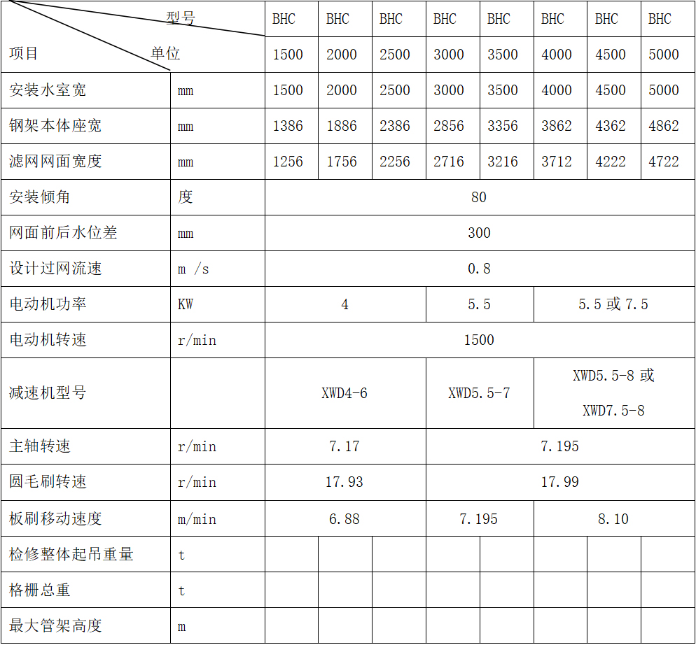
2. Main Technical Parameters:
Section 3: Structure and Working Principle:
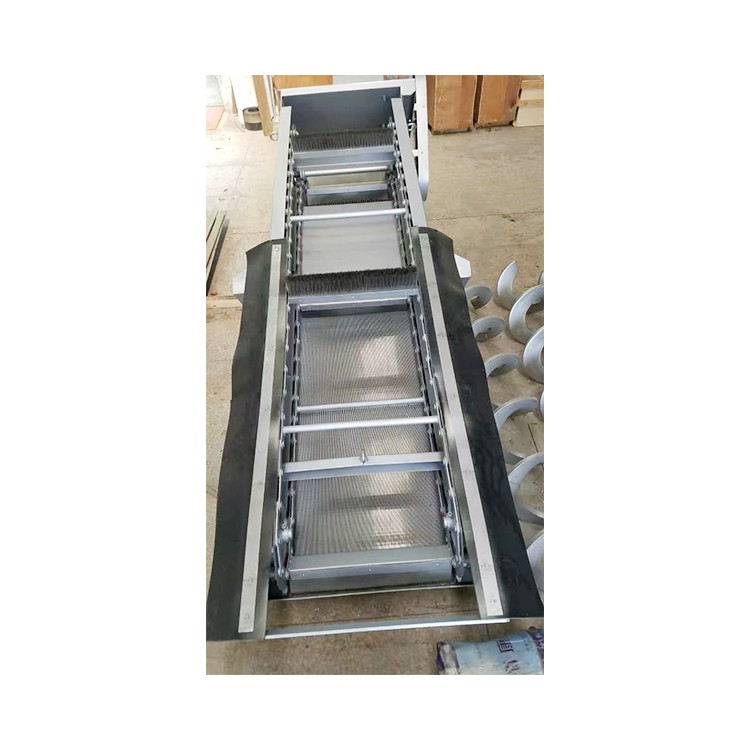
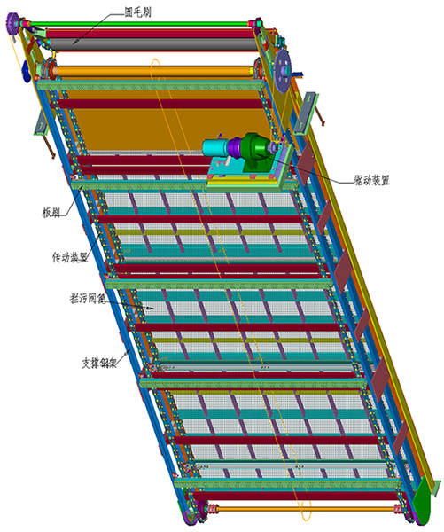
1. Structure:
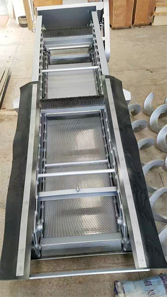
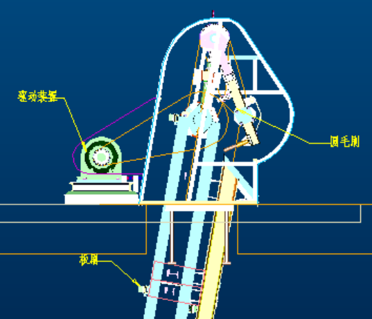
The BHC type grille consists of a supporting steel frame, a debris screen, a board brush, a round bristle brush, a driving unit, and a transmission unit, etc.
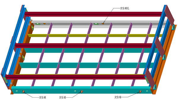
Supporting steel frame
This section consists of modular steel frame construction. Composed of two or more sections. Each frame section is equipped with locating pins and pin sockets for limitation, secured with bolts. During maintenance, the entire unit can be lifted out, or sections can be lifted individually.
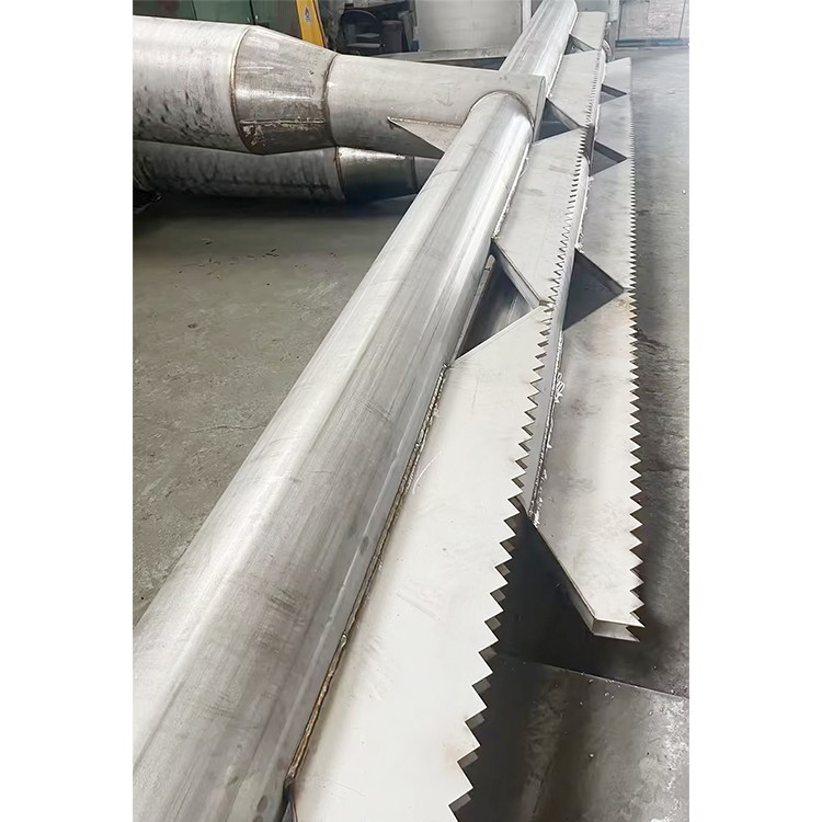
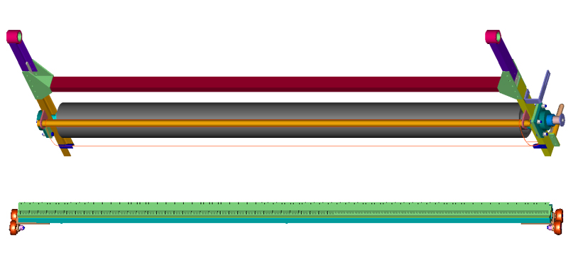
(2) Silt Trap Grating
The debris screen is a crucial part of the BHC type grille. Its function is to trap debris and purify the water flow. The screen is made of stainless steel material. The surface is flat, the gaps are even, and the wires are in an open state along the water flow direction, ensuring smooth water flow and easy debris trapping. The debris screen is divided into several sections and fixed on the frame, making the installation simple and reliable with convenient maintenance.
(3) Flat and round bristles brushes
Board brushes and round bristle brushes are the functional components of the entire grille, which clean debris such as weeds and dirt trapped in the mesh to the slag tank, achieving the purpose of cleaning and removing impurities.
(4) Drive Assembly
This grille is driven by an electric motor, which is reduced in speed by a planetary cycloidal pinion reducer, and then rotated by a single chain to drive the main shaft, thereby achieving the movement of the grille's operating mechanism.
(5) Transmission Section:
The transmission part of this grille is chain-driven. It boasts compact transmission, low load on the shaft, high load-bearing capacity, high efficiency, and suitability for harsh environments. It includes the following components:
Main drive section: Enables the up and down movement of the flat brush. Function: Clears debris from the grate.
Counter shaft part: Powers the rotation of the round brush. Function: Removes residual dirt from the board brush.
2. System Schematic
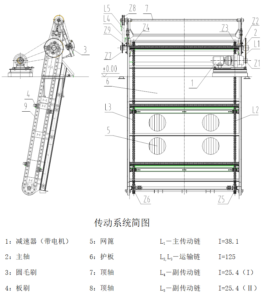
(1) Transmission System Schematic
(2) Working Principle:
Brushes driven by motor and propelled by the transport chain, tightly adhering to the mesh, move upwards from bottom to top, carrying away weeds and debris from the water flow and intercepted by the mesh with the brushes, transporting them through the protective plates on the frame to above the zero-meter level, achieving the goal of cleaning the water flow of impurities.
(3) Transmission Process:
The transmission process of the grid can be seen in the simplified transmission system diagram above. After the power is turned on, the motor and reducer begin to transmit power. Through the sprocket Z1 on the transmission device, it drives the chain L1, which then drives the main shaft 3 to rotate via sprocket Z2. The main shaft 3 causes sprockets Z5 and Z4 to move two conveying chains L2 and L3. Sprockets Z5 and Z6 are the driven wheels on the conveying chain, causing the chain and brush to rotate. The sprocket Z7 on the main shaft rotates with the main shaft, driving the auxiliary chain L4. It then passes through parallel sprocket Z8 to drive auxiliary chain L5, thereby causing sprocket Z9 to rotate the circular brush 4. When the brush hits the circular brush, the circular brush gradually opens up a certain distance from the center of the top shaft 7, and then, under the force of gravity, it exerts pressure on the brush to remove dirt. After passing through the brush, it automatically returns to its original position under gravity, completing a cleaning action. The removed dirt falls into the slag trough and is washed away by water, achieving the cleaning process throughout.
IV. Installation and Commissioning:
Installation:
(1) Inspect Parts: Before installation, first check if all parts are available according to the overall installation diagram and the requirements in the installation and operation manual.
(2) Single Pre-burying: Single pre-burying is the foundation for the installation and use of gratings. Therefore, during the single pre-burying construction, the position of the pre-burying components, the exposed shape, material, foundation, etc., must be strictly executed according to the process and technical requirements. Any changes must be协商 with the manufacturer for resolution.
(3) Rails: After the secondary embedded parts like rails are in place according to the drawings, first perform spot welding. Adjust the two rail channel steels using methods such as adjusting bolts, clips, or wedges. Ensure that the position error, straightness, inclination, and parallelism of the two rails meet the requirements of the drawings before proceeding with the assembly trial. The complete assembly frame should move freely without any obstructions when inserted into the rail channels. Only then should the rail channels and other secondary embedded parts be securely welded according to the drawings. After welding, recheck the movement of the assembly frame within the rail to confirm its functionality. If it still moves, the condition is good, and the secondary grouting of the embedded parts can be performed. If not, the cause should be identified and corrected.
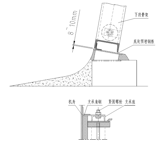
(4) After adjusting the secondary embedded parts, the exposed excess length of the adjustment bolt rod must be cut off (as shown in the figure below).

(5) Control of the frame thermal expansion gap and grouting of the side wing support seats: As shown in the lower part of the figure, the frame has an embedded steel plate gap △S=8mm from the bottom, considering the longer frame below the zero-meter level, the thermal expansion due to the difference between the installation closing temperature and the local extreme temperatures over the years. This must be strictly ensured during construction. During construction, a 8mm thick steel plate is placed on the bottom steel plate to elevate the grate, adjusting the level according to the upper and top sprocket shafts. The grate support seat is securely fastened to the support angle steel with bolts, and grout is poured into the pre-buried pit. After the grout sets, slightly lift the grate, remove the steel plate used for padding, thus ensuring the 8mm gap. (See figure below).
2. Grille Installation:
(1) Standard grilles are composed of two or more sections, which are non-interchangeable. When installing, each section should be numbered and installed sequentially according to the numbers.
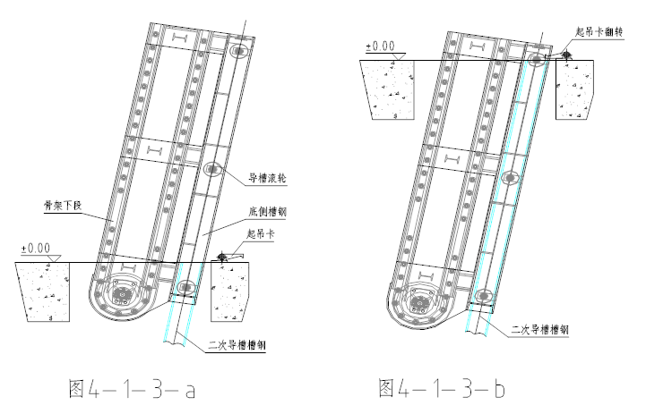
(2) Lower Body Hoisting: Align the two lower side槽钢 of the lower body with the pre-buried guide rail槽钢, allowing the槽钢, guide rail, and roller to fit into the secondary槽steel guide rail. Subsequently, slowly lower the lower frame while gradually inserting the body into the pit, as shown in Figure 4-1-3-a. When the top of the lower frame is level with the ground, flip the lifting frame to position the top of the frame on the pit opening surface, as shown in Figure 4-1-3-b.
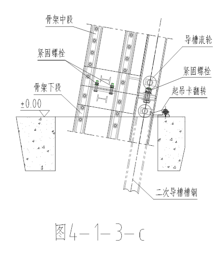
(3) Mid-section Hoisting Frame: Attach the hoisting wire rope to the hook on the upper bottom side channel steel, lift the fuselage, and after positioning with the pin and pin socket, connect the bolts in sections to securely fasten the lower and middle fuselage sections into one unit, as shown in the illustration (Figure 4-1-3-c). Then slightly lift the entire unit, rotate the hoisting clip, allowing the entire unit to slowly slide down along the pre-buried guide rails, until the end of the middle section is level with the ground. Next, flip the hoisting frame so that the end of the middle section frame is on the surface of the pit opening.
(1) The installation process on the upper section of the frame is the same as above.
(2) After the frame is fully inserted into the channel steel guide rail, move the frame up and down several times. After checking for no obstructions, proceed to weld and grout the rail.
(3) Install power unit
The power section is the driving part of the entire grille. It must be installed strictly according to the drawings. Pay attention to the center tilt of the motor, reducer, and drive chain sprockets in front, back, left, and right.
(4) Installation of transportation chain and brush
Each grate is equipped with two transport chains. During installation, first place the transport chain wheel shaft at the extreme position, then raise the large chain wheel shaft to the required position after the chains are hung. Brush pads are installed on the transport chains. To prevent the brush pads from being tilted after installation, adjust the large chain wheel shaft horizontally during the installation of the transport chains. This ensures that the brush pads are in a horizontal position after assembly.
(5) Installation of Other Parts:
Installation of other sections is based on the overall layout.
(6) Installation General Inspection:
Upon completion of installation, check each component and part item by item, according to the assembly drawing and the detailed list, to prevent the omission of any part or connecting components.
3. Tuning:
After the entire grille is installed, the front and rear water chambers of the grille must first be cleaned, removing all weeds, loose soil, and debris from the water chambers and the roller guide slots.
(2) Inspect the tension of each chain:
1) Loosen bolts 27 and 31, turn nut I with a long arm rod to ensure even tension in both conveyor chains. The chain should have a bending drop amplitude of 15-22mm between the two brush plates when in working condition (i.e., tensioned on the working side).
2) To tension the chain for the top sprocket and top double-row sprocket, first, adjust the angle of the tensioner bracket mounted on the top shaft to achieve initial tension. Then, move the position of the small chain tensioner to make the sag of the loose side about 1~1.5% of the distance between the centers of the two wheels. For the main drive chain from the reducer to the grille, you can adjust the tension by moving the frame deck of the motor base. When the working side is tensioned, the sag amplitude of the loose side chain is approximately 12~18mm.
3) Inspect and adjust the brush assembly to ensure the nylon bristles can fit into the mesh grid gaps by 2 to 3 mm for optimal cleaning performance.
4) Manually rotate the main shaft to check if all parts turn smoothly, for any signs of jamming or abnormal sounds. If any issues are found, locate the cause and resolve them.
5) Verify the motor's power connection is correct, then initiate an instantaneous start of the motor to check if the grille shaft rotation direction aligns with the shaft rotation direction shown in the overall drawing.
6) Connect the motor to the reducer according to the instruction manual for the limited torque hydraulic couplings.
4-2-2 Commissioning Run
(1) Empty-load test run
After the grille installation and adjustment are qualified, before filling water in the water chamber, a dry run test without load should be conducted for 30 to 60 minutes. Check if the motor current is stable, whether the motor no-load power is in line with (slightly higher) the factory test no-load power (record accordingly), and inspect if all rotating parts are functioning normally, for any collisions, abnormal sounds, vibrations, or overheating.
(2) Commissioning Test Run
After the empty-load trial run is approved, fill the grille water chamber with water, open the front and rear gates of the water chamber, then start the corresponding pump to keep the grille in the water filtering operation. In the water flow containing slag grass and debris, the grille should run continuously for one hour at the rated flow rate, with the water level difference before and after the grille not exceeding 20-40mm. Upon opening the condenser water chamber, there should be no weeds blocking at the steel pipe, indicating a successful working trial run.
(3) Perform normal differential pressure cleaning test:
When the grate operates at the rated excess flow rate, stop the brush blade, allowing debris and grass in the water source (if the water contains less debris and grass, similar debris can be manually added) to accumulate continuously on the grate. Once the water pressure difference before and after the grate reaches 200~300mm, insert the brush blade to start cleaning for about 5 minutes. If the water pressure difference before and after the grate can be reduced to below 20~40mm, the trial operation is deemed fully qualified.
Five, Usage and Maintenance:
1. Usage Requirements:
The grid is used in harsh environmental conditions. The quality of normal operation and maintenance directly affects the cleaning efficiency and lifespan. Therefore, the following points should be noted during operation.
(1) Based on the condition of debris and impurities in the water source, the brush should be regularly activated for cleaning. Simultaneously, the nozzle of the slag washing trough should be turned on to flush the debris and impurities from the trough to the designated area. If there is a high amount of debris in the water source, continuous cleaning can be performed.
(2) Regularly inspect the transmission unit and torque-limiting hydraulic couplings.
(3) During normal operation, if the actual power consumption of the motor exceeds 1.5 to 2 times the no-load test run power, check whether the transmission parts of the grate are functioning properly and if there are any weeds or debris caught underwater.
(4) Due to the conveyor chain that drives the brush pad wearing out over time, the chain may elongate. Therefore, it is necessary to frequently check the tension of the chain and ensure the proper operation of the transmission components, and make timely adjustments.
(5) When the grate is inoperative, if there is a high content of silt in the water source, close the gate or valve in front of the grate and take measures to remove the silt from the water source.
2. Maintenance:
(1) In addition to regular maintenance, the grille should undergo a major overhaul annually. Check the integrity and reliability of all fasteners, the smoothness of all transmission parts, if any wear parts need to be replaced, and apply anti-rust paint according to the drawings.
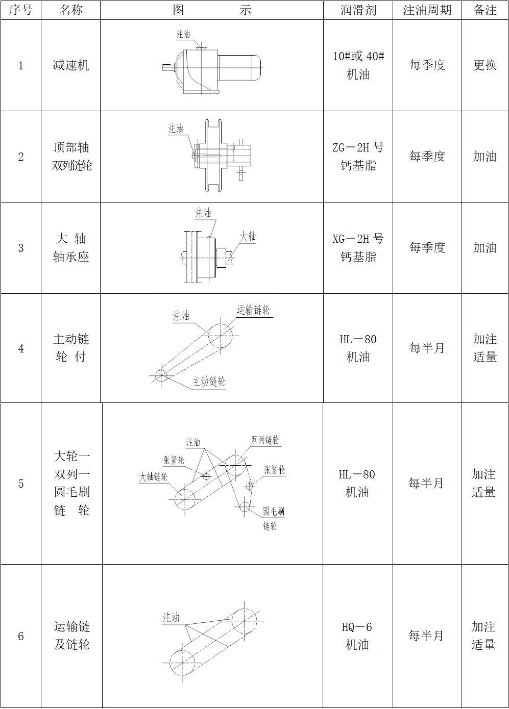
(2) After the grille is put into operation, lubrication should be performed regularly at all required lubrication points as per specifications (refer to lubrication points diagram).
Regularly observe the hydraulic couplings and planetary helical bevel gear reducers; immediately shut down for inspection if any abnormalities are detected.
(3) Each grille must be operated at least once within a specified time frame to prevent rusting from prolonged disuse.
(4) From the date of operation, a logbook must be maintained to record operational conditions, causes of incidents, and the handling or repair actions. It should also document issues and inspection findings from minor and major repairs.
3. Lattice lubrication area: