


I. Product Description and Application
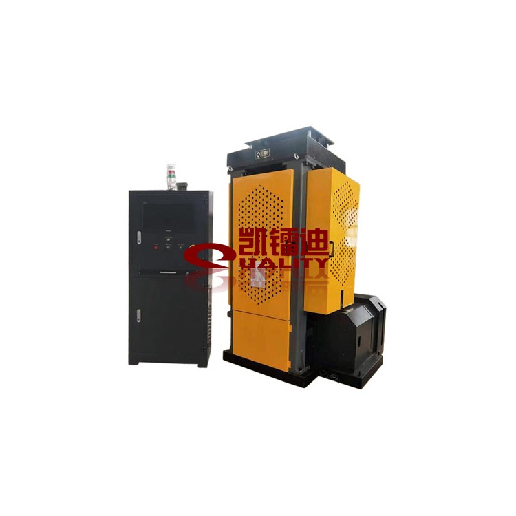
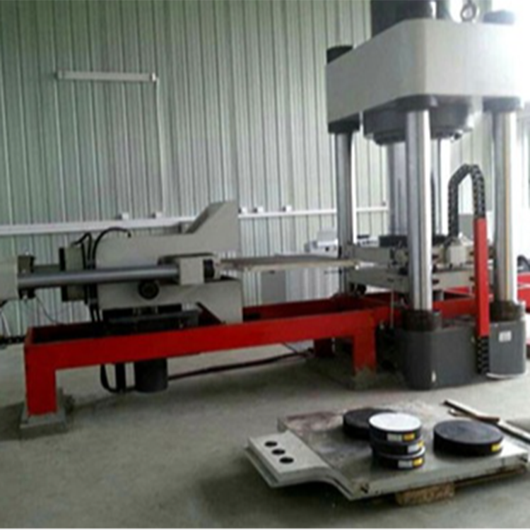
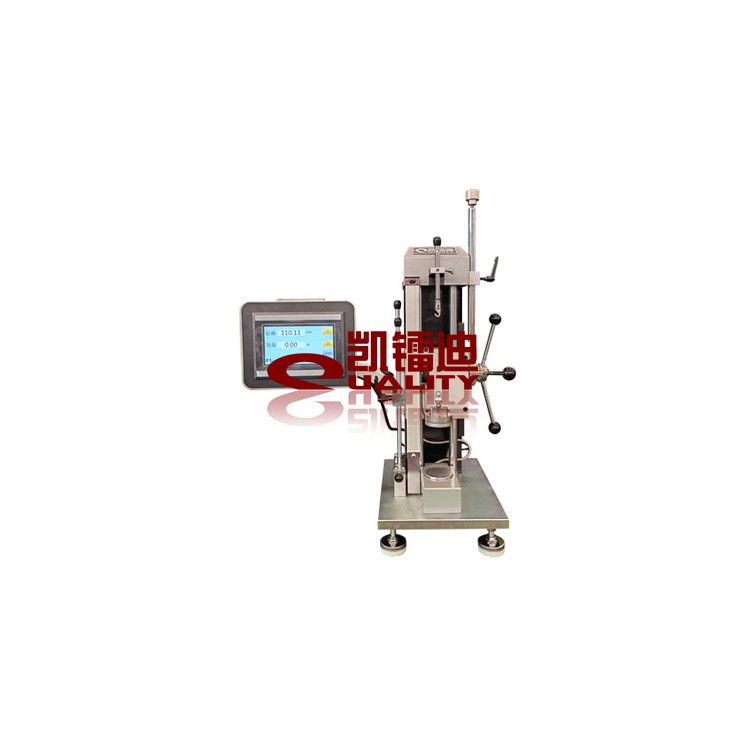
KPD(1121) Mechanical Fatigue Tester, primarily used for fatigue life testing of various helical springs and筒式减振器 used in cars, motorcycles, and other motor vehicles. Special fixtures can also be made to accommodate fatigue testing of special samples.
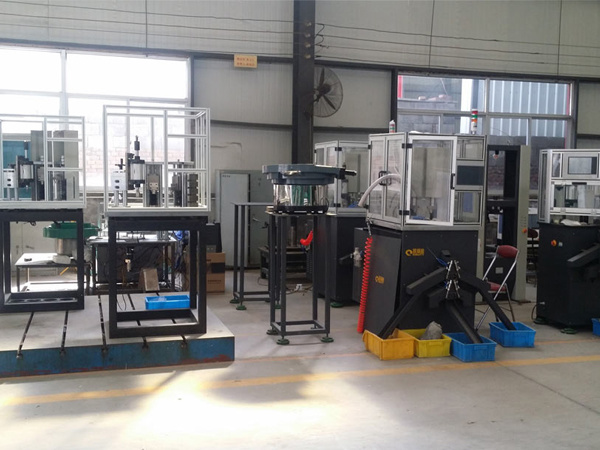
The main unit consists of four main parts: the frame, mechanical loading mechanism, transmission mechanism, and fixtures. It meets the requirements of various specimen sizes and specifications by adjusting the screw thread's rise and fall. Different installation methods for specimens are accommodated by changing the fixtures.
Adjust the amplitude and frequency according to the technical requirements of the spring.
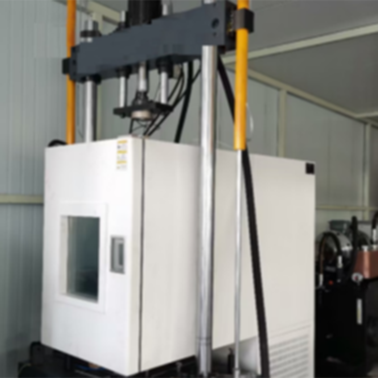
Additional temperature chambers can be provided for a fee, enabling fatigue life tests of springs at varying temperatures.
II. Product Features
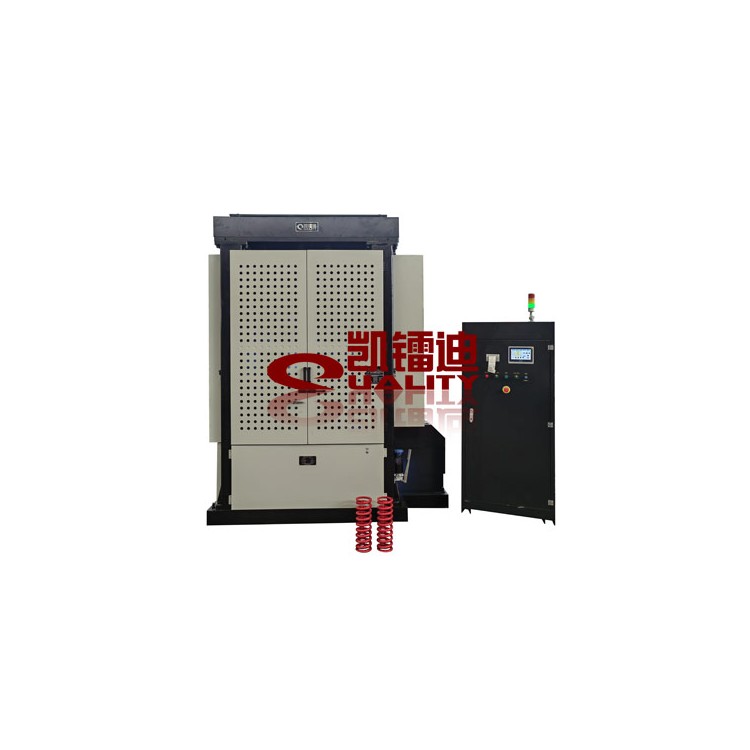
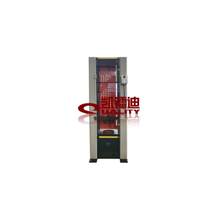
◇ Full machine loading capacity: 30kN, suitable for axial linear fatigue tests and axial impact fatigue tests of various passenger car suspension springs.
Four workstations.
◇ Electric adjustment of the test space, with added guide and locking mechanisms, effectively ensures rigidity of the loading area in spacious conditions.
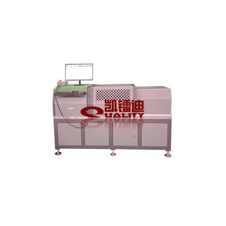
◇ Utilizes flywheel energy storage with a smooth clutch start, significantly reducing motor power and greatly cutting testing costs.
◇ Features variable frequency speed regulation technology, providing different test frequencies.
◇ Equipped with a continuous lubrication system, ensuring optimal lubrication for reciprocating moving parts.
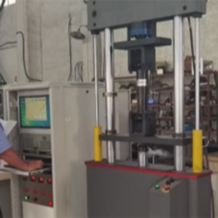
◇ Utilizing PLC control technology, there is a significant improvement in reliability and anti-interference performance compared to traditional control systems.
Touchscreen operation and display ensure clear test results and convenient operation.
Sensitive shutdown function for unattended operation.
◇ Equipped with a device status indicator light for clear visibility and remote monitoring.
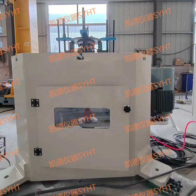
◇ Safety Protection Features:
All external equipment is protected by a safety net, each side can be independently opened, easy to adjust, and safe to operate.
2. At the eccentric adjustment mechanism, a safety switch is in place. The equipment cannot be powered on during amplitude adjustment operations. The switch must be turned off after adjustment to enable the equipment to start.
III. Main Technical Parameters
Please contact us for details on relevant parameters!