


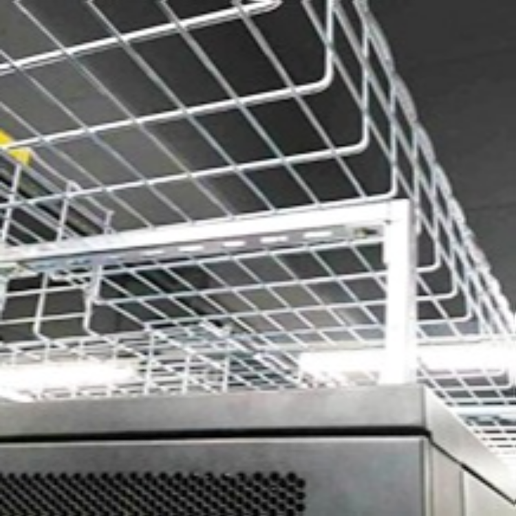


“Long ChangProduct Introduction and Design & Production Process of Brand Grid Bridge Fitting
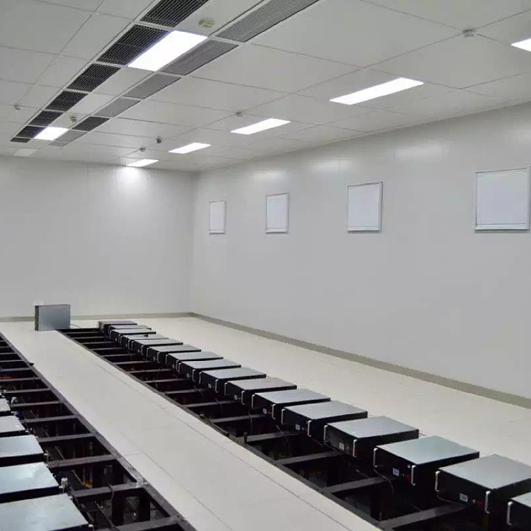
“Long ChangBrand Grid Bridge FittingAccording toCable Tray and Ladder System for Electrical InstallationIEC 61537 StandardDesign and production。Suitable for overhead installations of power cables, control cables, lighting wiring, and data cables in data centers, both indoor and outdoor.
The product boasts a variety of advantages::
1. Brand new look, versatile assembly, aesthetically pleasing, innovative and unique, eye-catching, offering a refreshing sensation.
2. This product is suitable for installation under various conditions, offering convenient, flexible, quick, and simple wiring, maintenance, and upgrades. It meets stringent quality and installation standards, greatly facilitating the process.
Customers find it easier to manage cables.
3. The "easy to deform" structure and "quick assembly components" significantly reduce the time required for bridge installation and cable wiring.
4. Effectively reduces the impact of electromagnetic interference.
5. Utilizes its designed structure for more efficient and safe air circulation, no water accumulation, and no dust buildup.
Design, production, testing standards and requirements:
We offer a variety of material options for our current products.:
1008,195F,Q235,301,304,3042,316,316L。
Surface treatments include electroplated zinc, environmentally friendly zinc plating, color zinc, blue zinc, white zinc, zinc-nickel plating, hot-dip zinc.
Powder coating, electrolytic polishing (stainless steel).
1) The metal grid cable tray is composed of steel wires in both longitudinal and transverse directions, with the smaller steel wire diameter being:
4mmDiameter for width not exceeding150mmBridge Support
4.5mm diameter for bridge channels width of 200mm
5mm diameter for bridge channels with a width of 300mm
6mm diameter for bridge channels measuring 400mm, 450mm, 500mm, and 600mm in width.
2) Top steel wires on both sides of the bridge structure are used in the “TForm weldingForm a safe margin.
3) Each grid size of the bridge is 50mm x 100mm
4) Bridgeway installation methods include suspension, wall-side mounting, underfloor or cable trench installation. Larger support components have a wider installation spacing.2.5mAnd shall not exceed the maximum load-bearing capacity specified by the manufacturer for the cable tray.
5) The average tensile strength at all welding joints is 500 kg.
6) Testing
a). In accordance with European standardsCEI/61537, the load-bearing and deformation characteristics of the bridge must be tested and the results announced.
b). Must undergo independent testing to determine if the support parts are suitable forCat6 Data cables.
c). As perE30/E90Standard compliance fire resistance test.
d). The electrical continuity of the connecting components must be tested using known methods and results.
Surface Treatment
i). Electroplated GalvanizedBSEN 12329-2000Level 2) Suitable for indoor installation;
ii). Galvanized Zinc Coating ThicknessBS 729) At60To80Within micrometers;
iii). Stainless Steel AFNOREZ CND 17.2 /AISI 316L)
Test Requirements: Refer toROHS Directive 2002/95/EC and subsequent amendments.
Test Method: Refer toIEC62321/2ndCDV(111/95/CDV):Procedure for Determining the Content of Restricted Substances in Electronic and Electrical Products
(1) Determine cadmium content using ICP
(2) Determine lead content using ICP and AAS.
(3) Determine mercury content using ICP
(4) Determine the content of hexavalent chromium using the spot test method/colorimetry.
Test Results:
Test Results of Chemical Method (Unit:mg/kg)
Test Items | Method (see) | 1 | MDL | ROHS Limitations |
Cadmium (Cd) | (1) | ND | 2 | 100 |
Lead (Pb) | (2) | ND | 2 | 1000 |
Mercury (Hg) | (3) | ND | 2 | 1000 |
Spot test/Boiling water extraction method for hexavalent chromium (CrVI)) | (4) | Negative | See Note (4) | # |
Test Part Appearance Description:
1、 Silver blue metal
Note:
(1) mg/kg = parts per million (ppm)
(2) ND = Not Detected
(3) MDL = Limit of Detection
(4) Spot Testing Method:
Negative = Hexavalent Chromium Not Detected in Coating, Positive = Hexavalent Chromium Detected in Coating
When the spot test result isNegative or uncertain results will be further verified using the boiling water extraction method.
Boiling Water Extraction Method:
Negative = Hexavalent Chromium Not Detected in Coating
Positive = Hexavalent chromium detected in the coating, indicating that the concentration of hexavalent chromium in the boiling water extract of the tested sample with an area of 50 cm² is equal to or greater than 0.02 mg/kg.
(5) #= Positive indicates the detection of hexavalent chromium on the tested sample.
Negative indicates no hexavalent chromium detected in the tested sample.
Reference to a higher permissible limit2002/95/EC RoHS Directive and subsequent amendments, 2005/618/EC.
Test Conclusion: Based on the tests conducted on the samples submitted, the results are in compliance with the EUIn compliance with the requirements of Directive 2002/95/EC (ROHS) and subsequent amendments.
Hot-dip galvanized
Inspection Criteria:Cable Bridge for Electric Control and Distribution - JB/T10216-2000
Order Number | Inspection Project | Single Position | Standard Regulation | Test Results | Single Item Determine | |
1# | 2# | |||||
1 | Coating Thickness | um | ≥65 | 70 | 67 | Qualified |
2 | Adhesion | Grade | The galvanized layer should not exhibit any peeling, scaling, or bulging upon lever testing. | Compliant | Qualified | |
3 | 48-hour salt spray test | Grade | After 48 hours of salt spray test, not less than the 3 specified in Table 6 of JB/T6743-1993. | 3 | Qualified | |
Inspection Conclusion: The sample has been inspected and all items meet requirements.Requirements as specified in JB/T10216-2000 standard.
Product Load Capacity Comparison Table
Iron-made:
Specs (MM) | Load Capacity (KG/M) | Note | |
Standoff spacing: 1.5 meters | Stand spacing: 2 meters | ||
30*50(100) | 10 | 7 | |
30*150 | 12 | 7.5 | |
30*200 | 16 | 10.5 | |
30*300 | 22 | 13 | |
54*50(100) | 20 | 13 | |
54*150 | 30 | 20 | |
54*200 | 39 | 30 | |
54*300 | 67 | 40 | |
54*400(500) | 105 | 65 | |
54*600 | 122 | 70 | |
105*100 | 41 | 30 | |
105*150 | 60 | 45 | |
105*200 | 80 | 55 | |
105*300(400) | 120 | 83 | |
105*500(600) | 145 | 90 | |
Stainless steel made:
Specification (MM) | Load Capacity (KG/M) | Note | |
Spacing between brackets: 1.5 meters | Spacing between brackets: 2 meters | ||
30*50(100) | 9 | 6 | |
30*150 | 11 | 7 | |
30*200 | 15 | 9 | |
30*300 | 21 | 14 | |
54*50(100) | 21 | 15 | |
54*150(200) | 25 | 18 | |
54*300 | 46 | 28 | |
54*400 | 70 | 45 | |
54*500(600) | 105 | 75 | |
105*100(150) | 39 | 24 | |
105*200 | 62 | 42 | |
105*300 | 75 | 55 | |
105*400 | 110 | 75 | |
105*2500(600) | 135 | 90 | |
Note:
1) The values in the table are not complete figures.
2) When the spacing of the bracketsAt 1.5 meters, the drop distance from the bridge's center to the origin is not more than 7.5MM when carrying the weight specified in the load table. At a bracket spacing of 2 meters, the drop distance from the bridge's center to the origin is not more than 10MM when carrying the weight specified in the load table.
3) Due to stainless steel's greater toughness compared to iron, its load-bearing capacity is relatively lower.


