


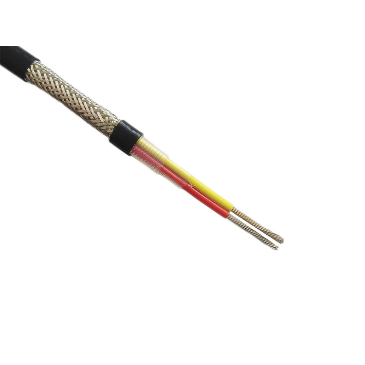


The heating element of the constant power parallel electric trace heater is a tightly and uniformly wound heating wire around the insulated busbar. The heating wire is connected sequentially to the busbar at fixed intervals (heating section length), forming a parallel circuit with stable power along the length of the busbar upon voltage application.
In constant power parallel heating cables, continuous heating resistive wires form a series of continuous parallel heating sections – heating sections, each of which is independently operable and can be cut to size as required (except for fire-resistant constant power parallel heating cables).
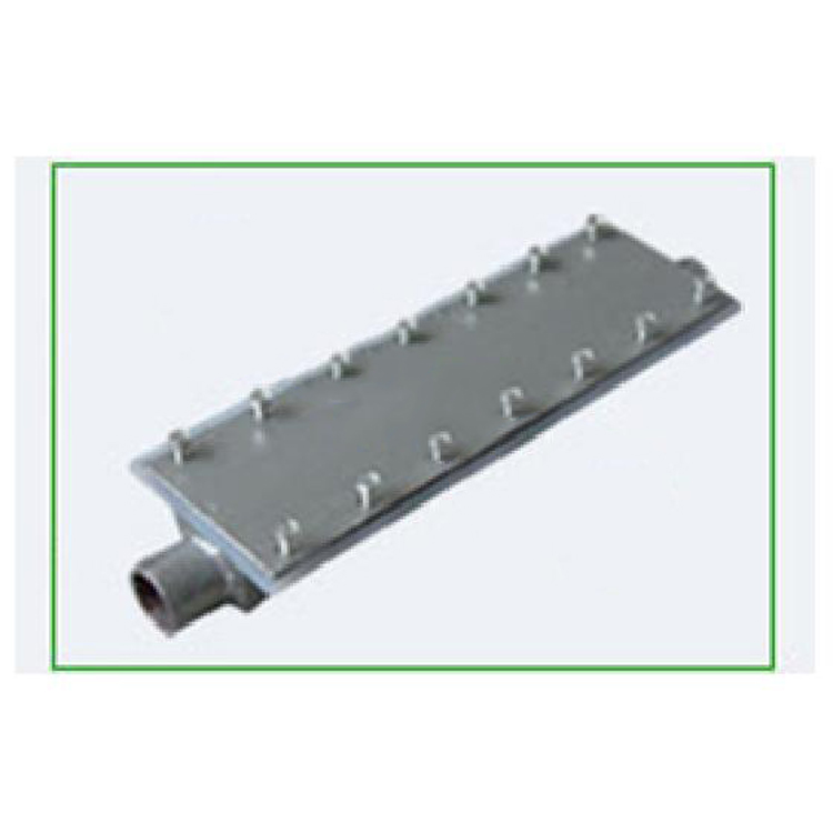
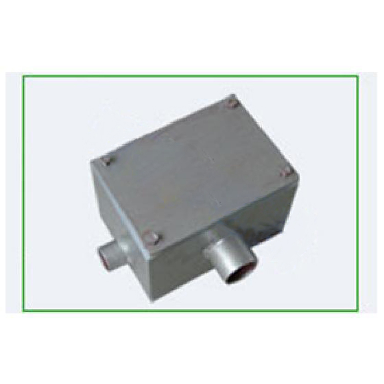
Constant power parallel heating cable products cannot be used alone; they must be paired with a suitable explosion-proof temperature controller and accessories that are compatible with the environment.
In areas with explosive gas T4 groups in Factory Zones 1 and 2, the explosion-proof temperature controller's set temperature should not exceed 110°C. The temperature sensor is mounted on the outer sheath at a high temperature point to ensure the surface temperature of the electric heating tape does not exceed 130°C.
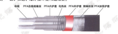
Constant Power Parallel Cable Heater Structural Diagram
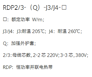
1. Constant Power Parallel Heating Cable Model Description
2. Constant Power Parallel Electric Heat Tracing Main Technical Parameters
| Model | Single-phase constant power | High Temperature Single Phase Constant Power | Three-phase constant power |
| Project | Parallel electric heating tape | Ratio parallel heating cable | Parallel electric heating tape |
| Rated Output Power | 10/15/20/25/30/35/40/45/50/55/60 W/m | ||
| Explosion-Proof Marking | Ex e IIC T4 Gb | ||
| Rated Voltage | 220V | 220V | 380V |
| Dielectric Strength: | ≥2000V/min non-breakdown | ||
| Insulation Resistance: | ≥50MΩ/hm | ||
| High temperature resistance. | 205℃ | 260℃ | 205℃ |
| Low installation temperature: | ≥-40℃ | ||
3. Constant Power Parallel Electric Heat Tracing Performance Comparison Table
| Project | Temperature Resistance Grade | Maintain temperature | Utilize length |
| Model | |||
| RDP2-(Q)-J3-10 | 205℃ | ≤150℃ | 195 m |
| RDP2-(Q)-J3-20 | 205℃ | ≤120℃ | 140 m |
| RDP2-(Q)-J3-30 | 205℃ | ≤90℃ | 115 m |
| RDP2-(Q)-J3-40 | 205℃ | ≤65℃ | 90 m |
| RDP2-(Q)-J4-20 | 260℃ | ≤180℃ | 140 m |
| RDP2-(Q)-J4-30 | 260℃ | ≤150℃ | 115 m |
| RDP2-(Q)-J4-40 | 260℃ | ≤120℃ | 90 m |
| RDP3-(Q)-J3-30 | 205℃ | ≤120℃ | 275 m |
| RDP3-(Q)-J3-40 | 205℃ | ≤100℃ | 235 m |
| RDP3-(Q)-J3-50 | 205℃ | ≤80℃ | 210 m |
| RDP3-(Q)-J3-60 | 205℃ | ≤60℃ | 180 m |
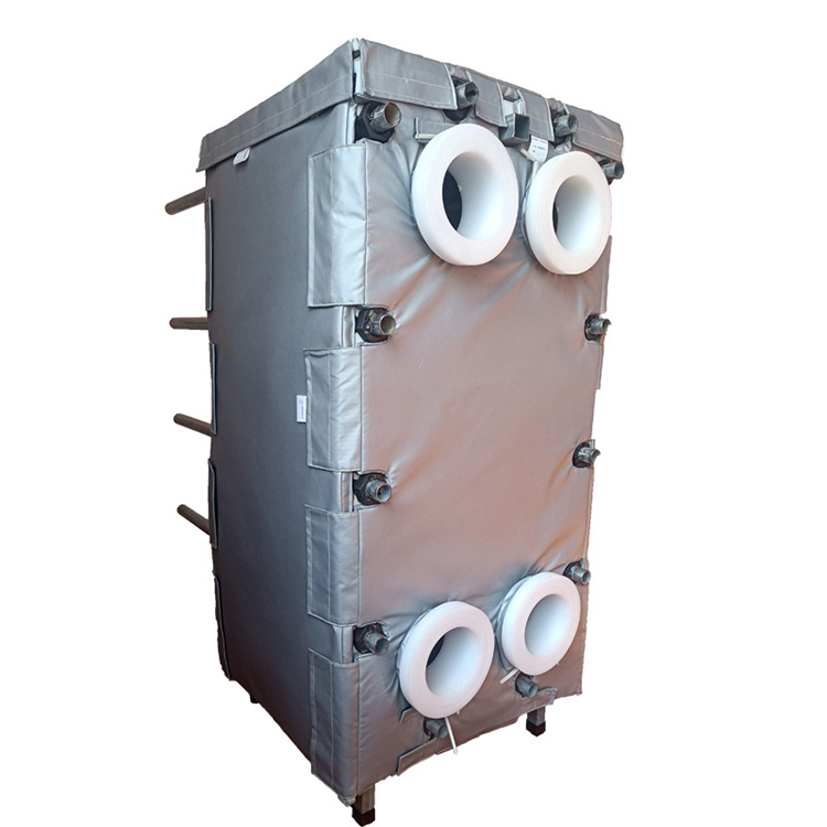
4. Application Sites:
Constant power parallel electric heating cables are suitable for pipeline and equipment frost and condensation prevention in the following situations:
· Safe Zone;
· Hazard Zones 1 and 2; Zones 21 and 22;
·Humid, salt fog environment; corrosive environment.


