


GSH1500 Explosion-proof Mining Speed Sensor

I. Main Applications
The GSH1500 explosion-proof mine speed sensor (hereinafter referred to as the speed sensor) is a non-contact sensor capable of measuring the speed of shafts, impellers, and gears with geared disks. It boasts advantages such as the ability to measure low speeds, high conversion accuracy and reliability, small size, and easy installation. It is used for measuring and controlling the speed of various power equipment and can transmit data remotely for use with other secondary instruments and computerized measurement and control systems.
II. Environmental Conditions for Use
The speed sensor should operate reliably under the following conditions:
a. Environmental temperature: -10°C to +40°C
b. Average relative humidity not exceeding 95% at (+25℃).
c. Atmospheric Pressure: 80~106 KPa
d. Applications with no significant vibration or impact.
e. In environments where there is no severe dampness, waterlogging, or insulation damage from corrosive gases.
f. Working in environments where there are explosive mixtures of gas and coal dust in underground coal mines.
III. Explosion-Proof Type
Explosion-proof Type: Mine Used Intrinsically Safe Type Explosion-proof Mark: Ex ibⅠMb
IV. Model Meaning
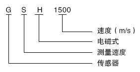
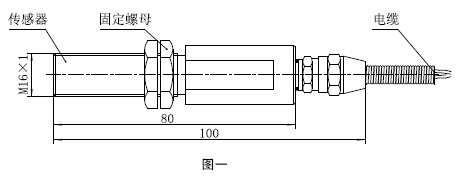
Section 5: Dimensions, Weight, and Installation Sizes
a. Dimensions (Length x Outer Diameter): 100 mm x 22 mm
b. Weight: approximately 0.5 kg;
c. Installation Dimensions: Fixed Screws: M16x1.
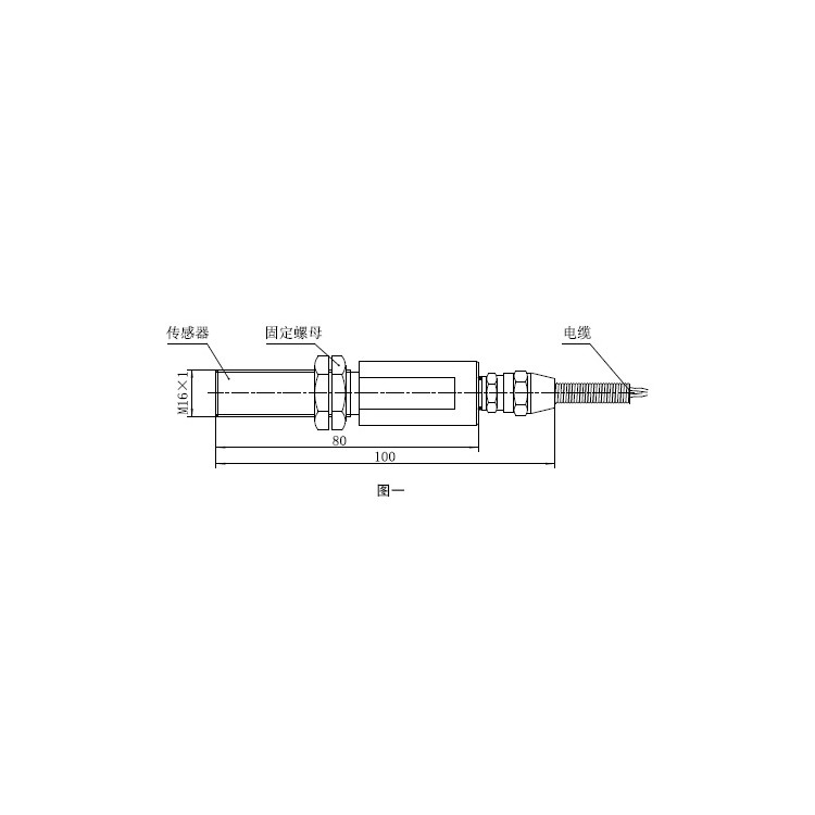
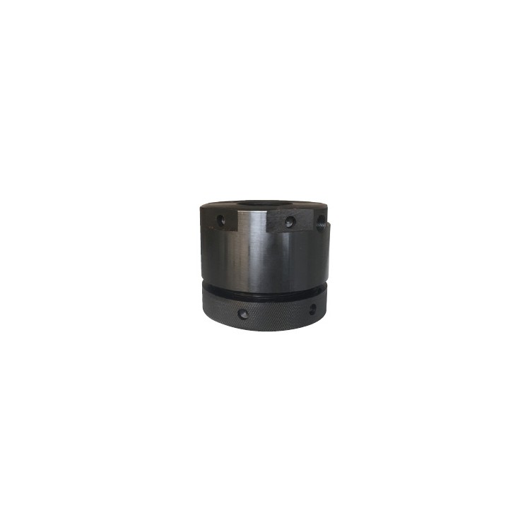
Six, Outline Drawing

Section 7: Structural Features
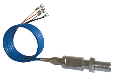
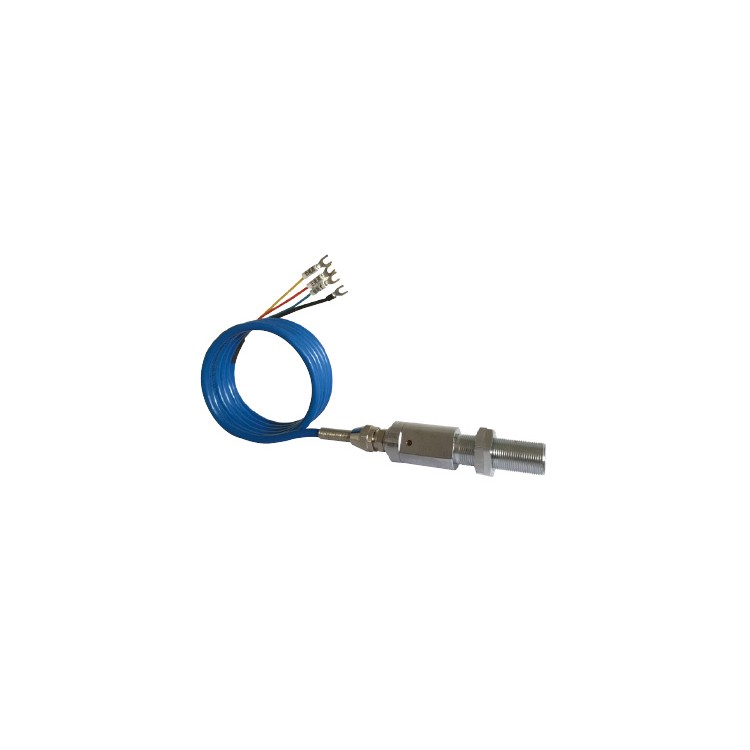
The speed sensor is composed of the housing, fixing bolt, and nut (see Figure 1 for the external view).
Section 8: Working Principle
This sensor converts magnetic signals into electrical signals, which are then processed by a PLC or microcomputer for speed display and output of corresponding frequency signals.
Section 9: Technical Specifications
a. Rated Working Voltage: DC 12V, 24V
b. Operating Current: ≤40mA; (Operating current less than 50mA is supplied by a secondary instrument or a switching power supply.)
Speed Range: (0 ~ 5000) r/min
d. Measurement Error: ±3% FS
e. Continuous Frequency Signal Output: (0~100) Hz, Low level not greater than 0.5V, High level not less than 7V (Pull-out Current 2mA)
f. Function: Converts rotational speed to frequency signal for output to the superior equipment.
g. Frequency Response Range: 20Hz - 5KHz
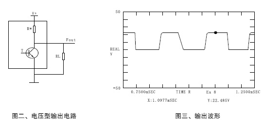
h. Output Characteristics: The sensor outputs a square wave pulse with a duty cycle of approximately 50%, with pulse amplitude (fout): low level less than 0.7V, high level (RL=10KΩ) greater than or equal to 90% of the power supply voltage. The final output circuit is shown in Figure 2, and the output waveform is shown in Figure 3.
Ten. Measurement Principle
Measurement Principle (f is the output frequency signal in Hz, n is the number of teeth of the object being measured, and r is the rotational speed of the object in rpm) When the number of teeth of the object being measured is 60, the output frequency signal equals the rotational speed of the object
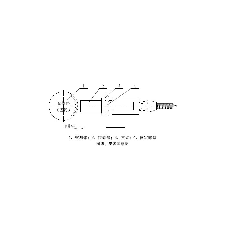
Eleven: Installation and Commissioning
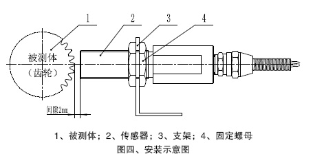
a. The sensor is positioned by an M16×1 thread, as shown in Figure 4 for installation requirements.
b、Wiring lead color coding: Power V+ - Red (White), Signal fout - Blue (Green), Ground (Black) ) - Yellow (Black) Shielded Ground
 Metal Shielding Mesh
c. Sensors have undergone relevant debugging before shipment. For detailed configuration during use, please contact our company promptly.

Twelve, Important Notes
Please carefully read this manual and keep it for future reference.
b. Follow all warnings and instructions labeled on this product.
c. This product is a precision instrument; strictly prohibited from attempting to repair the product yourself.
d. No alteration of the model, specification, or parameters of components within the intrinsic safety circuit of the product is permitted.
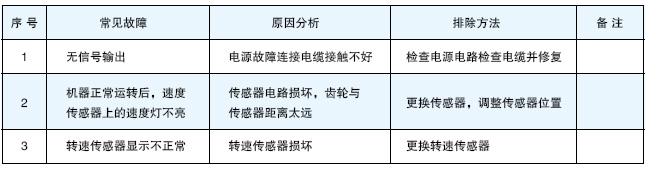
Chapter 13: Fault Analysis and Troubleshooting
Section 14: Maintenance and Care
a. When in use, it is mandatory to assign personnel to handle the daily maintenance and care of the product.
b. Maintenance personnel must carefully read the "User Manual," familiarize themselves with the internal and external structure, as well as the circuit principles of the equipment.
c. Maintenance and service personnel should regularly inspect the reliability of the equipment's circuit connections.
Fifteen, Maintenance
When equipment malfunctions, conventional methods may not resolve the issue. Please do not attempt to repair it yourself and contact our company promptly.
Sixteen: Quality Assurance
The speed sensor is covered by a one-year free repair or replacement warranty from the date of shipment from the factory, provided the user follows the instructions for proper use.