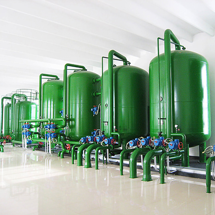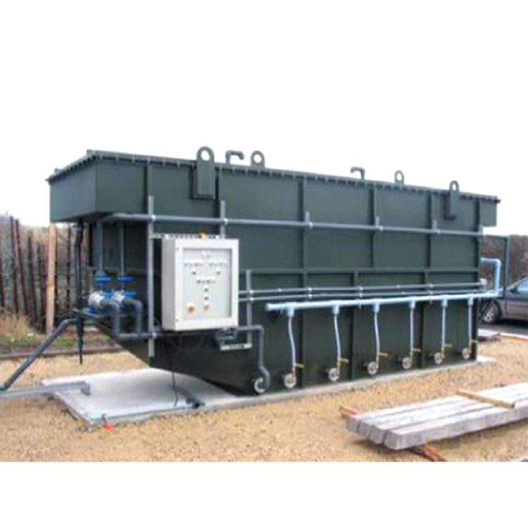


Mixed-bed ion exchange unit

Structure Overview
One. The regeneration of the anion exchange resin is conducted by feeding the alkali regeneration solution into the main pipe above the level of the anion exchange resin by 300mm (for Φ400, 500, and 600, a single main pipe is used for feeding; for Φ800 and 2500, a double main pipe is used). The solution is distributed through small holes in the pipe, and the exterior of the pipe is covered with a 60-mesh nylon mesh fabric. The regeneration of the cation exchange resin with acid is achieved by draining through the drainage caps on the porous plates of the bottom drainage device.
Section 2: Middle Section Device
The middle section device is set at the interface between the anion and cation resin beds, designed for regeneration effluent of acid and alkali, as well as flushing. The design type is either double main pipe or branch main pipe style, with each tube having an outer covering of plastic window fabric and a layer of 60 mesh nylon mesh.
Three, Drainage Equipment: Equipped with PB2-500 type stacked drainage caps on porous plates, or pagoda-shaped ABS drainage caps. The material of the porous plates varies according to the equipment specifications. (Φ400, 500, 600 models use rigid polyvinyl chloride porous plates, while Φ800, 2500 models use steel-lined rubber porous plates).
Four, the inlet and outlet pipe diameters are designed for a flow velocity of 1.5 meters per second within the pipeline.
Five, Resin Backwashing Swelling Rate: Due to the varying backwashing swelling rates of anionic exchange resins, based on practical operating experience, a backwashing swelling rate of one hundred percent is used. At the interface between the anion and cation resins, one sight glass is installed on the resin surface layer and at the height of maximum backwashing swelling, for observing the resin surface and the backwashing resin conditions.
Six, Resin Transportation: Both the intake and discharge of resin are considered to be hydraulically transported. A resin intake port is set at the upper part of the cylinder, and a resin discharge port is located near the porous plate at the lower part of the cylinder.