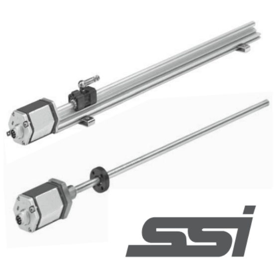


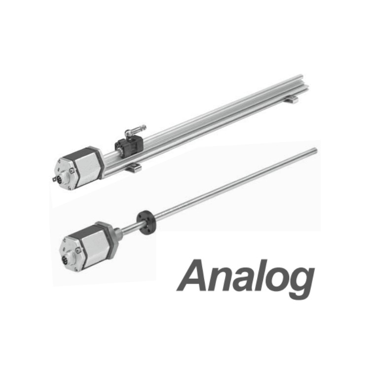


Utilizing magnetostrictive technology, equipped with an RS422-SSI digital output interface.
The magnetic blocks have no electrical contact, ensuring almost limitless lifespan with minimal wear.
High performance in environmental protection, IP protection, and EMC immunity.
In comparison to non-linear, reproducibility, and hysteresis, the measurement boasts high precision.
High vibration and shock resistance, suitable for harsh industrial environments.
Electromagnetic Compatibility (EMC) 2014/30/EU
■ Compliant with RoHS 2011/65/EU
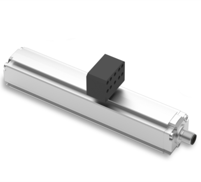
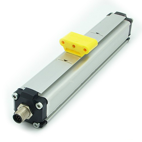
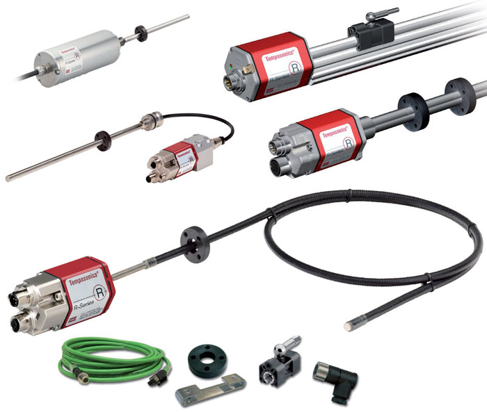
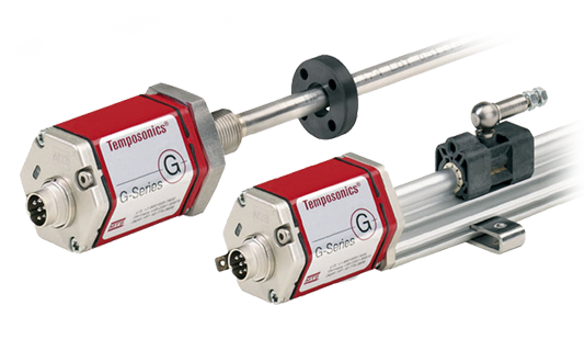
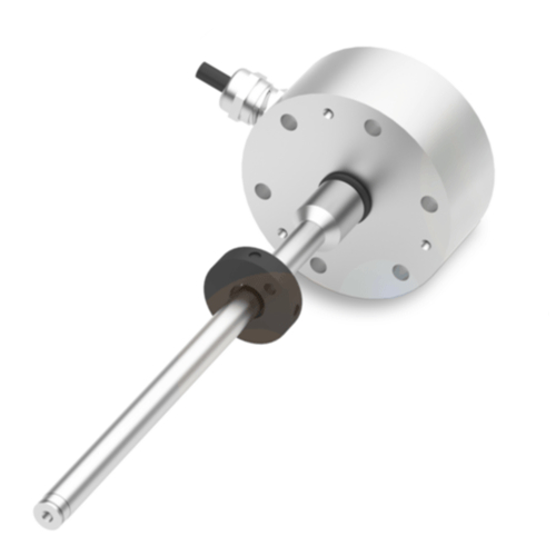
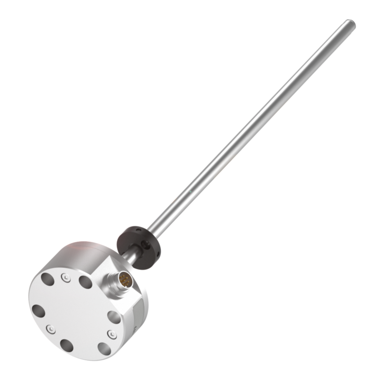
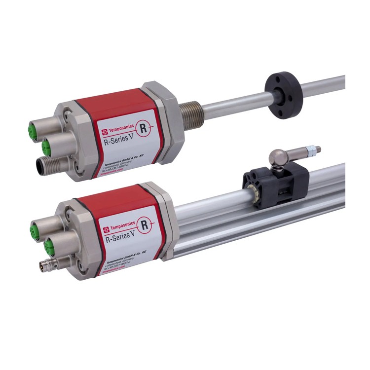
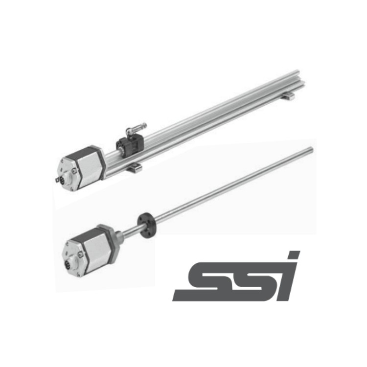
This rugged and wear-resistant non-contact EP linear displacement sensor ensures excellent durability in harsh industrial environments and provides accurate position measurement results. Borsen's specialized sensor department produces high-quality waveguides to guarantee the precision of position measurement.
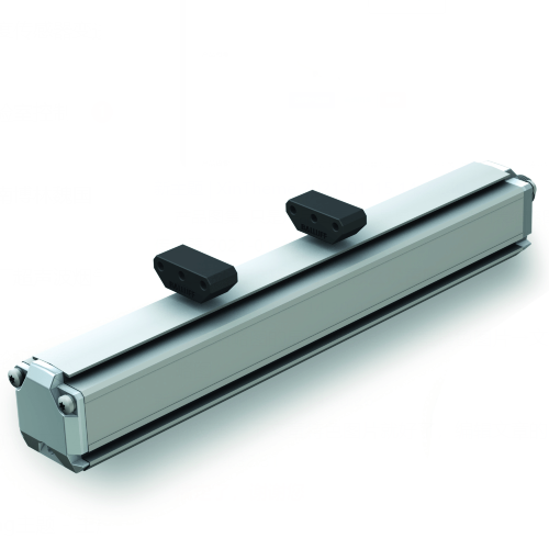
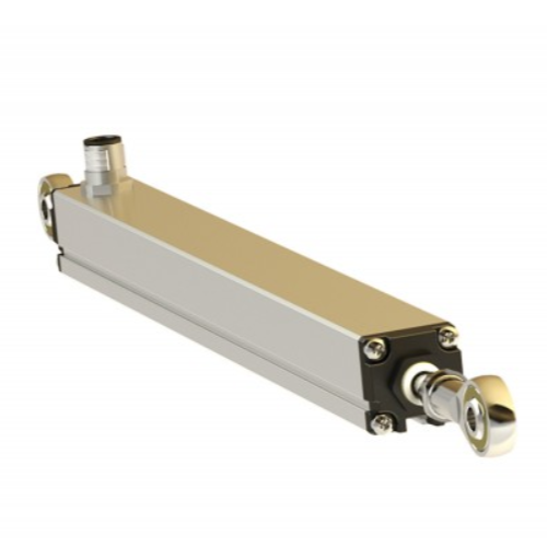
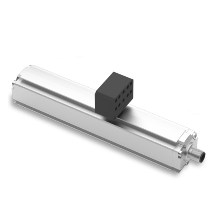
Compact EP-type sensors are designed for standard applications and are particularly suited for profile structures with limited installation spaces. The diagnostic electronic components are housed within an aluminum sensor casing. Typical applications of this sensor include the plastic industry, metal forming, wood processing, and factory automation.
| Output | |
| Interface | SSI (Synchronous Serial Interface) |
| Data Format | Binary or Gray code |
| Data Length | 24/25/26 positions |
| Data Transmission Rate | 70 kBd ~ 1 MBd, cable length dependent: Wire Length: <3 <50 <100 <200 <400 m, Speed: 1000 <400 <300 <200 <100 kBd |
| Measurement value | Location |
| Measurement Parameters | |
| Resolution | 1 / 2 / 5 / 10 / 20 / 50 / 100 µm |
| Cycle Time | |
| Linear Accuracy | Magnet Slider: ±0.02% FS (±50μm min), Floating Magnet: ±0.02% FS (±60μm min), High Floating Magnet: ±0.03% FS (±70μm min) |
| Repeat Accuracy | ≤±0.002% of full scale (±20μm) |
| Working Conditions | |
| Operating Temperature | -40...+75℃(-40…+167°F) |
| Humidity | Relative humidity 90%, no condensation |
| IP2,3 | P67 (Under proper installation of the matching connector) |
| Impact Test | 100g (single impact) IEC 60068-2-27 standard |
| Vibration Testing | 15g/10...2000Hz, IEC60068-2-6 standard (resonant frequency excluded) |
| EMC Testing | Electromagnetic Radiation Test based on EN61000-6-3, Electromagnetic Interference Test based on EN61000-6-2; Sensors comply with EU directives and bear the CE mark. |
| Magnet movement speed | Magnet Slider: ≤5 m/s; (High) Floating Magnet: Any value |
| Design/Material | |
| Sensor electronic component housing | Aluminum |
| Sensor Profiles | Aluminum |
| Trip Length | 50...5000mm |
| Mechanical Installation | |
| Installation Location | At any location |
| Installation Instructions | Removable Fixed Clamping Plates (to be secured with M5 screws) |
| Electrical Connections | |
| Connection Type | Direct line or M12/M16 male connectors |
| Working Voltage | +24VDC(-15/+20%) |
| Wavy pattern | ≤0.28Vpp |
| Energy Consumption | Typical Value: 45mA |
| Insulation strength | 500VDC (DC ground to machine ground) |
| Polarity Protection | Up to -30VDC |
| Overvoltage Protection | Up to 36VDC |
SSI Synchronous Serial Interface
The sensor meets all the requirements of the output encoder for the SSI standard. Position values are transmitted at high speed to the control system in a 24/25/26-bit encoding mode. One of the main functions of SSI is to facilitate synchronous data conversion, which is easily achievable in a closed-loop control system. The controller generates a clock pulse train to initiate sensor data transmission: position data is sent one bit at a time to the controller with each clock pulse received by the sensor. Position data is continuously updated within the sensor and then converted into serial information via a shift register.

EP Type Housing Dimensions and Installation Instructions

Description: (1) The number of fixing clips required for installation corresponds to the range. It is recommended to add one clip for every 500mm increase in range.
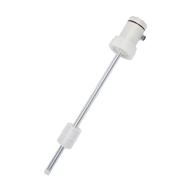
(2) Position measurement for EP series products uses floating magnets: directly mounted on moving parts, not in contact with the sensor. Allows for ±3mm lateral offset and up to 10mm vertical gap.
Sensor wiring method
When mating航空插头, define by the pin and the corresponding wire color.
Waterproof connector direct wiring, defined by wire color
D70 connector pin layout (facing the sensor head)

| Needle Size | Line color | Definition |
| 1 | Gray | Data (N/A) |
| 2 | Powder | Data (Plus) |
| 3 | Yellow | Clock (+) |
| 4 | Green | Clock (-) |
| 5 | Brown | +24VDC(-15%/+20%) |
| 6 | White | DC Power Supply Ground |
| 7 | No service |