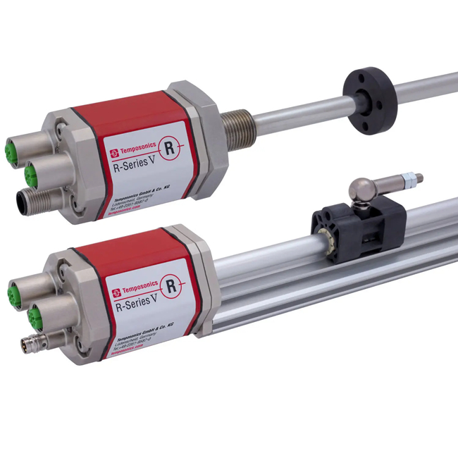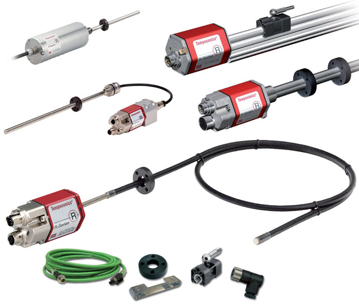


Robust and Reliable Industrial Position Sensor
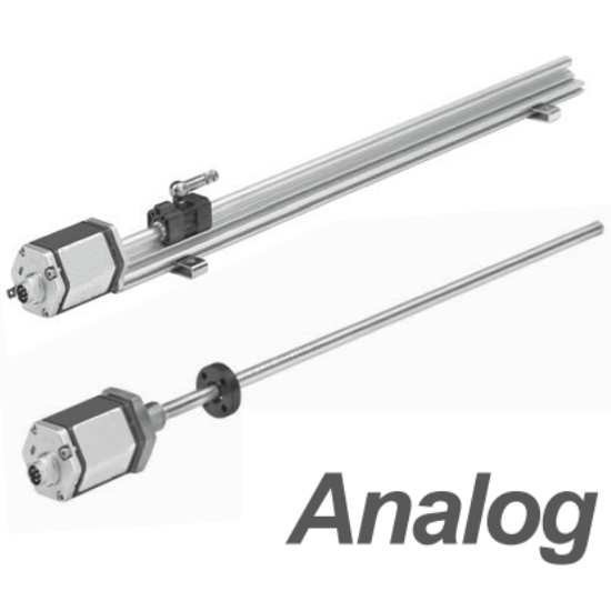
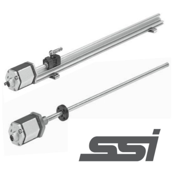
Linear measurement, output
LED indicator lights provide diagnostic functions
Touchless measurement, no wear and tear
High precision, with a resolution as high as 2 µm
■ Non-linearity up to 0.01%
■ Repeated accuracy up to 0.001%
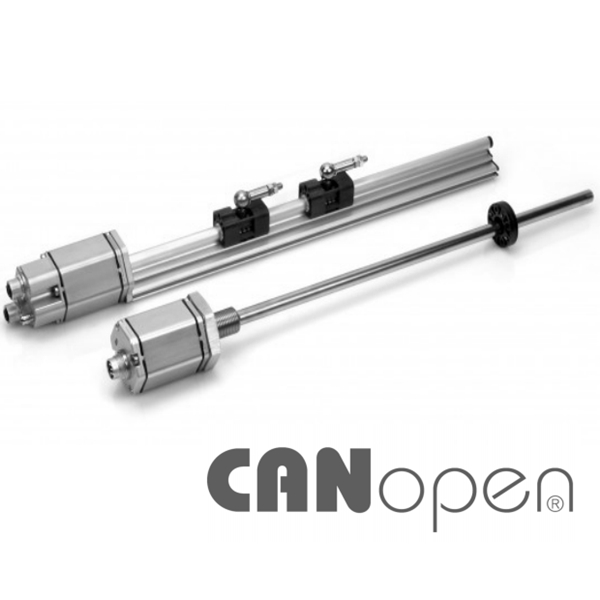
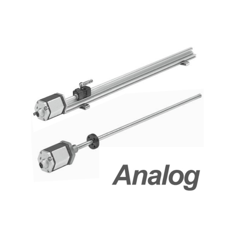
■ Standard CAN Bus Output
| Parameters | Specs |
| Input | |
| Measurement Data | Location, speed |
| Measurement Range | RP Aluminum Molding Shell: 50 - 5080 mm; RH Pressure Resistant Outer Tube: 50 - 7620 mm |
| Output | |
| Interface | CAN Bus System Protocol, ISO DIS 11898 |
| Data Format | CANopen: CIA Standard DS-301 V4.02 Encoder Profile DS-406 v3.1 CANbasic: CAN 2.0 A |
| Transmission Speed | Speed: 1000, 800, 500, 250, 125, 50, 20 kbit/s; Line Length: <25 <50 <100 <250 <500 <1000 <2500 m (Users can freely change the transmission speed via programming software.) |
| Overvoltage Protection | 36Vdc |
| Accuracy | |
| Resolution | 1 / 2 / 5 / 10 / 20 / 50 / 100 µm |
| Non-linearity | < Soil content up to 0.01% (Fine soil 50 pm) |
| Repetitive accuracy | Full range ± 0.001% (small ± 2.5 pm) |
| Temperature coefficient | < 15 ppm / °C |
| Lag | < 4 µm |
| Work Conditions | |
| Operating Temperature | - 40 to +75 °C |
| Humidity / Dew Point | Humidity 90%, no condensation |
| Protect | RP Aluminum Molding Shell: IP65 Pressure-resistant Outer Tube: IP67 (Connector must be tightly locked) or IP68 (Optional straight-out cable) |
| Impact Index | 100 g (Single impulse) / IEC Standard 68-2-27 |
| Oscillator Indicator | 15 g / 100 - 2000 Hz / IEC Standard 68-2-6 (Durability) |
| EMC Testing | Radiation EN 50081-1, Immunity EN 50082-2, EN 61000-4-2/3/4/6, Grade 3/4, Class A, CE Certified |
| Magnet Speed | Any |
| Structure, Material | |
| Fault Indicator | Electronic end caps with LED display |
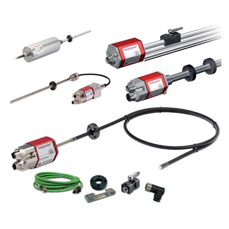
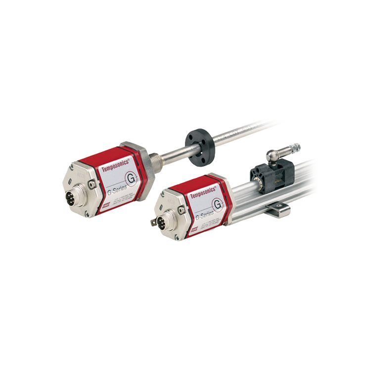
| RP Aluminum Molding Shell | Sensor Head: Aluminum, Sensor Rod: Aluminum, Position Magnet: Slider Magnet or Floating Magnet |
| RH Pressure-resistant Outer Tube | Sensor Head: Aluminum Sensor Rod and Flange: 304L Stainless Steel Outer Tube Pressure: 350 bar / 690 bar (Peak) Position Magnet: Ring Magnet, Floating Magnet, or Buoyant Ball |
| Installation | |
| Installation Location | Any direction |
| RP Aluminum Molding Shell | Removable Fixed Clip (to be secured with M5 screws) |
| RH Pressure-resistant Outer Tube | Metric with screw thread flange M18 x 1.5 or British 3/4"- 6 UNF-3A |
| General locking force | 45 N-m |
| Electrical Connections | |
| Connector selection | 6-Pin D60 Connector or Direct Cable |
| Input Voltage | +24 Vdc (-15 / +20%) |
| Polarity Protection | -30 Vdc |
| Overpressure Protection | 36 Vdc |
| Power consumption | Typically within 100 mA |
| Fluctuation | < 1 % S-S |
| Electrical shock magnitude | 500 V (DC ground to mechanical housing ground) |
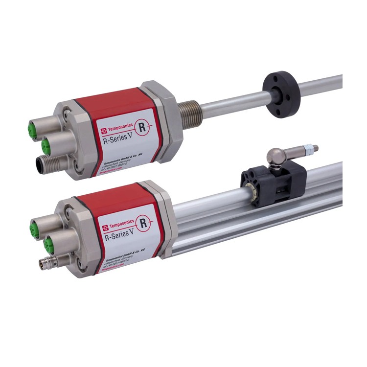
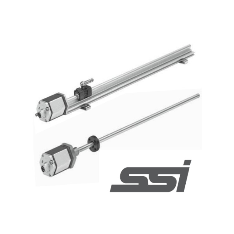
The R-series RP and RH linear position sensors, as a slave, comply with the Canbus (ISO 11898) protocol standard. The sensors directly convert position data into bus-oriented data and send it to the controller. The bus interface is suitable for transmission rates less than 1 Mbps. The software integrated in the sensor supports highly customizable CANopen, CANbasic, and other sensor bus systems.
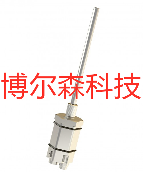
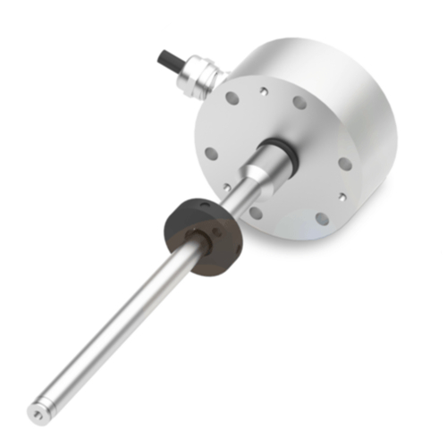
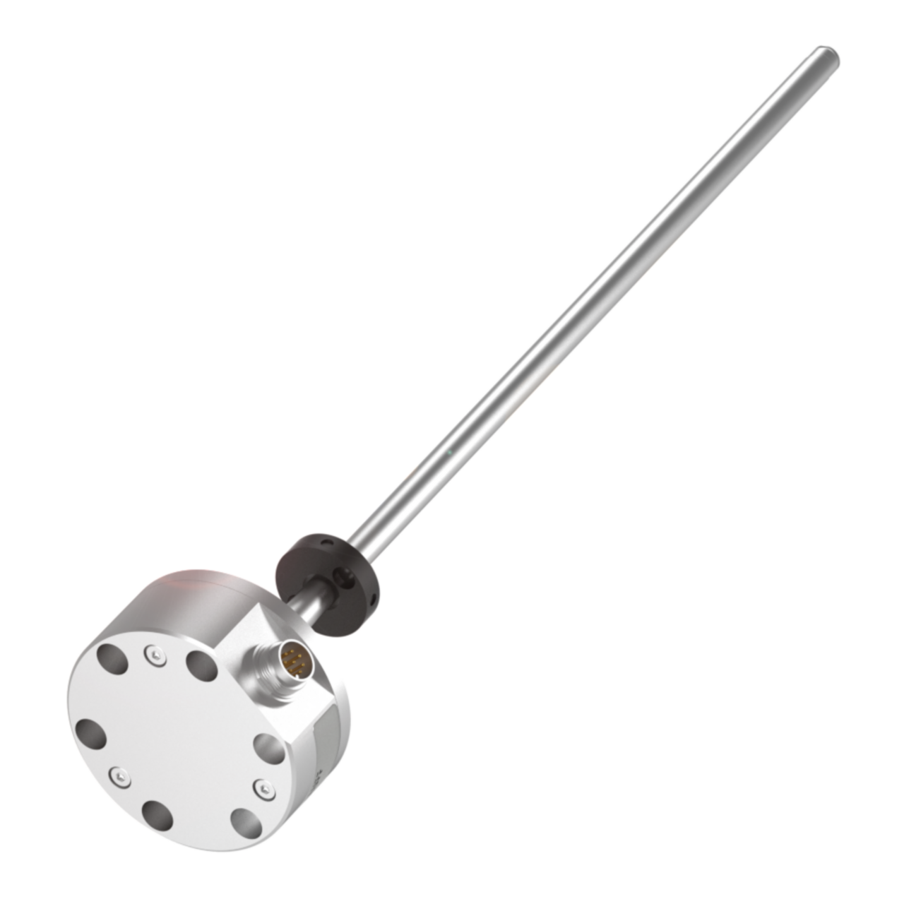
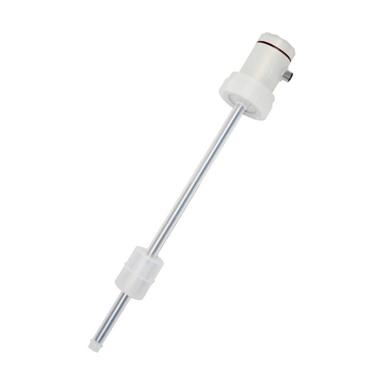
Pressure-resistant outer tube dimensions and installation instructions
RH series pressure-resistant outer casing, aluminum profile electronic chamber, designed specifically for hydraulic system use, internally mounted within the hydraulic cylinder, capable of withstanding pressure up to 34MPa continuously (69MPa peak). Available with thread specifications M18×1.5, M20×1.5, or 3/4”-16 UNF-3A.

Note: The upper and lower dead zones shown in the diagram indicate that the sensor outputs a zero or unreliable value within this area. The upper and lower dead zone values for this sensor are 50.8 and 63.5mm respectively, which can be appropriately modified according to customer requirements. This can be specifically requested from our sales or technical staff when placing an order.
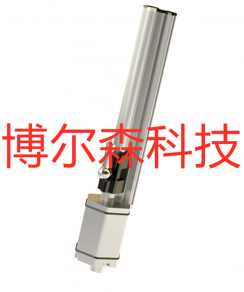
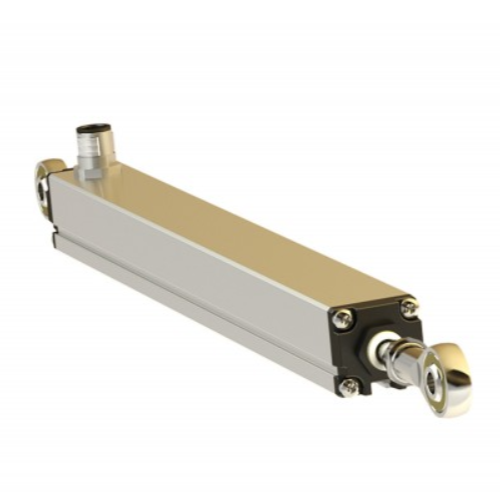
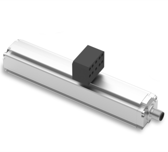
Aluminum Extrusion External Structure Dimensions and Installation Instructions
RP aluminum extrusion external mounting structure, suitable for general machinery, easy to install, and maintain.

Sensor wiring method
When mating aviation connectors, define by the pin and the corresponding wire color.
Waterproof connector directly exiting with wire color definition