


Robust and Reliable Industrial Position Sensor
Linear Displacement Measurement, Output
■ Contactless measurement, no wear and tear
Non-linearity less than 0.02%
■ Repeatability accuracy up to 0.001%
EMI interference resistance and CE certification
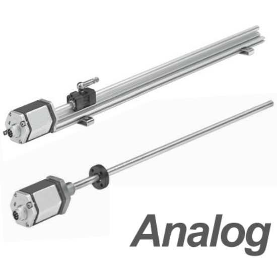
Simulated Output: Voltage or Current
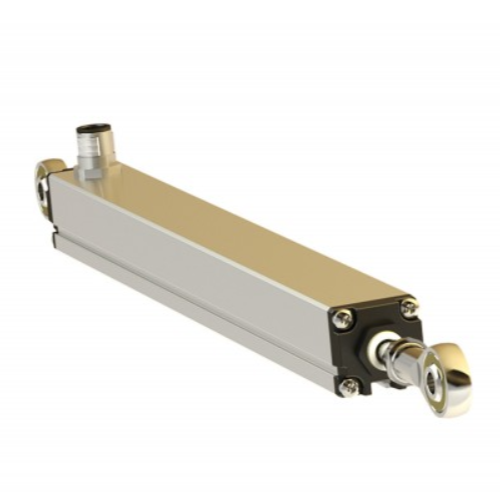
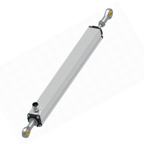
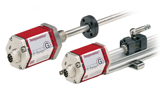
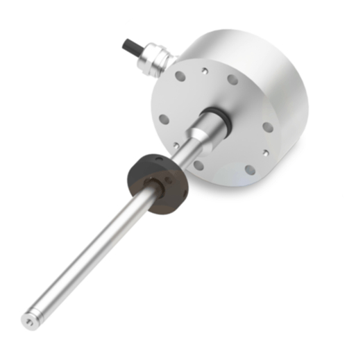
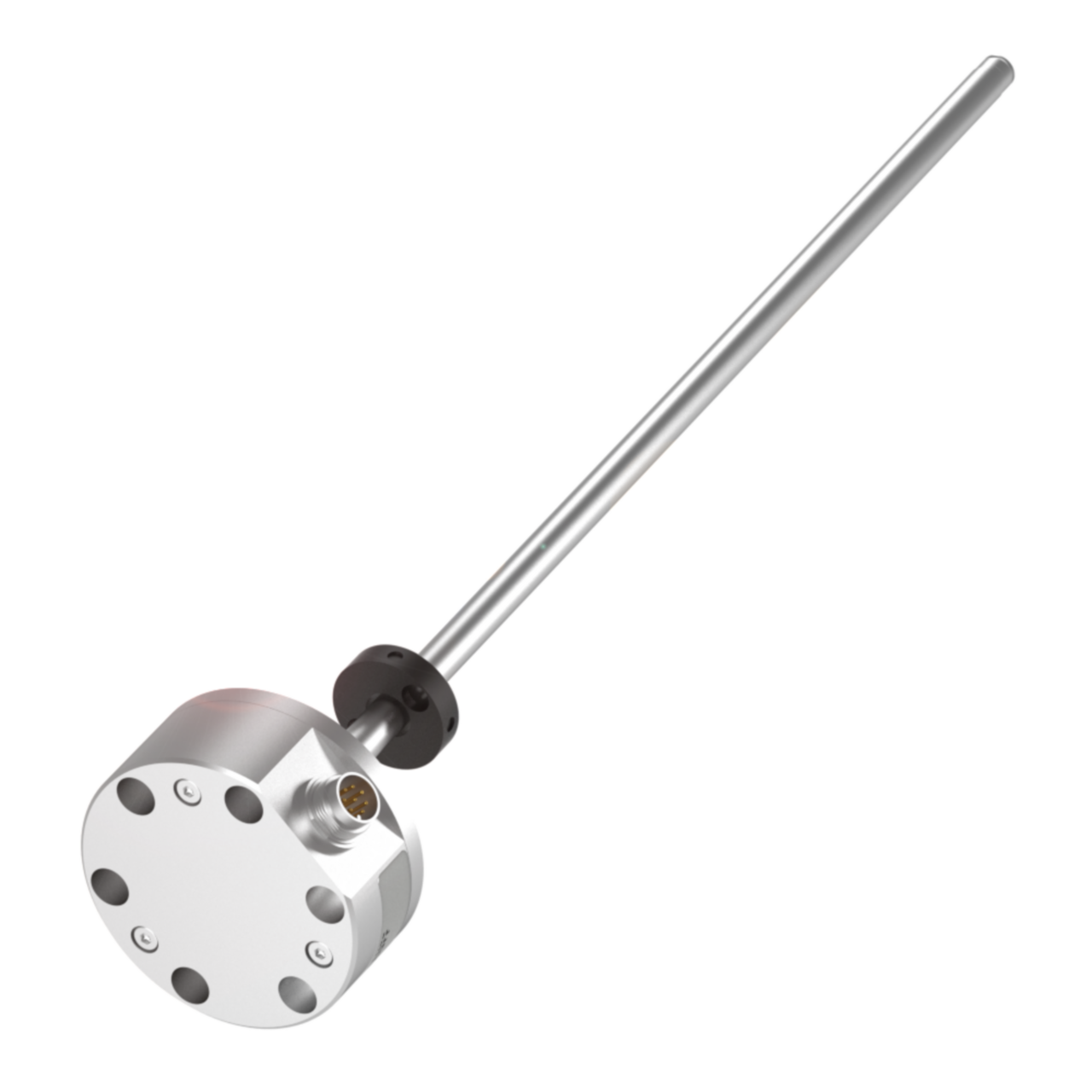
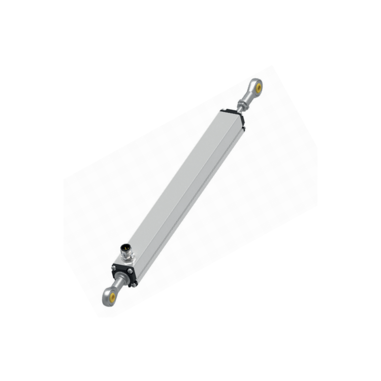
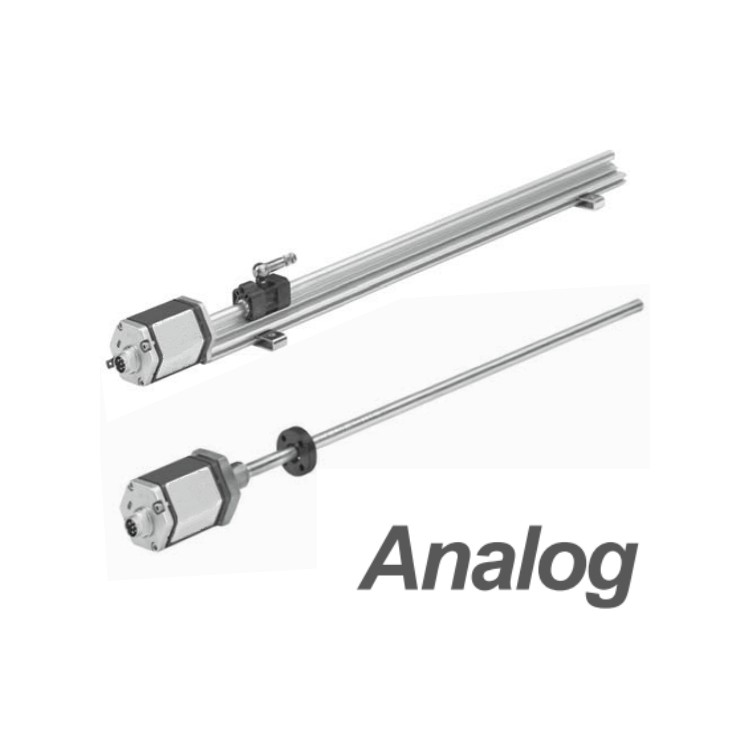
ER Type Integrated Telescopic Rod Design
The ER type displacement sensor is an integrated push-pull rod in design and function. The stainless steel piston rod is robust, capable of withstanding certain loads, and will not rust, ensuring a long service life. The non-contact position magnet is installed at the rear end of the sensor's piston rod, protected by an aluminum housing and immune to environmental contamination. The ER housing meets IP65 standards and CE certification.
Suitable for general machine tool installation or external cylinder mounting. Users can also add adjustable ball sockets at both ends of the sensor, ensuring compatibility even when the sensor is connected to movable mechanical components. The ER type provides stable and accurate repetitive output without regular maintenance, enabling continuous operation of the user's production line, thereby increasing output and reducing waste and downtime. It is one of the choices to replace encoders, LVDTs, and resistive potentiometers.
| Parameters | Specs |
| Input | |
| Measurement Data | Location |
| Measurement Range | 50 ~ 3500 mm |
| Output | |
| Voltage | 0 ~ 10 Vdc, 10 ~ 0 Vdc, -10 ~ +10 Vdc, +10 ~ -10 Vdc (Controller Low Load: > 5k ohms) |
| Current | 4 ~ 20 mA or 20 ~ 4 mA (Low/High Load: 0/500 Ohms) |
| Accuracy | |
| Resolution | Unlimited (depending on the controller's D/A conversion and power fluctuations) |
| Non-linearity | Full Range ± 0.02% (Dust 60 pm) |
| Repeatability accuracy | Full range ± 0.001% (± 2.5 pm) |
| Last Updated | >1.5 kHz |
| Fluctuation | Full Scale (F.S.) Range: 0.01% F.S. |
| Work Conditions | |
| Magnet Speed | At your service |
| Operating Temperature | - 40 to +75 °C |
| Humidity, Dew Point | Humidity 90%, no condensation allowed |
| Protect | IP65 ( mating connectors must be tightly secured) |
| Shock Index | 100 g (single impact) / IEC Standard 68-2-27 |
| Oscillator Indicator | 15 g / 100-2000 Hz / IEC Standard 68-2-6 (Durability) |
| EMC Testing | Radiation EN 50081-1, Immunity EN 50082-2, EN 61000-4-2/3/4/6, Grade 3/4, Class A, CE Certified |
| Structure, Material | |
| Electronic Head | Aluminum |
| Sensor rod | Stainless Steel 303 |
| Positioning Magnet | Built-in integrated |
| Installation | |
| Installation Location | Any direction |
| Installation Type | Adjustable Mounting Clip |
| Electrical Connections | |
| Connector Selection | 6-Pin DIN Connector or Straight Cable |
| Input Voltage | +24 Vdc (-15 / +20%) |
| Power consumption | 50 - 140 mA (range dependent) |
| Fluctuation | < 1% peak |
| Electrical shock quantity | 500 V (DC ground to machine ground) |
ER Type Shell Dimensions and Installation Instructions

Important Note: To prevent potential damage to the sensor, a nut or washer must be installed to prevent the slider rod from entering the aluminum housing when fully retracted into the sensor.
Fixed Clip

Sensor wiring method
When mating aviation connectors, define by pin and corresponding wire color.
Waterproof connectors are directly wired, defined by wire color.
D60 male connector pin arrangement (facing the sensor head)

| Needle size | Line color | Definition |
| 1 | Ash灰 | Analog Signal Output |
| 2 | Powder | Signal Ground |
| 3 | Yellow | Communication Interface (+) |
| 4 | Green | Communication Interface (--) |
| 5 | Brown | +24VDC(-15%/+20%) |
| 6 | White | Direct Current (DC) Power Supply接地 |