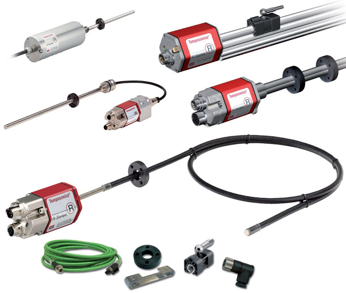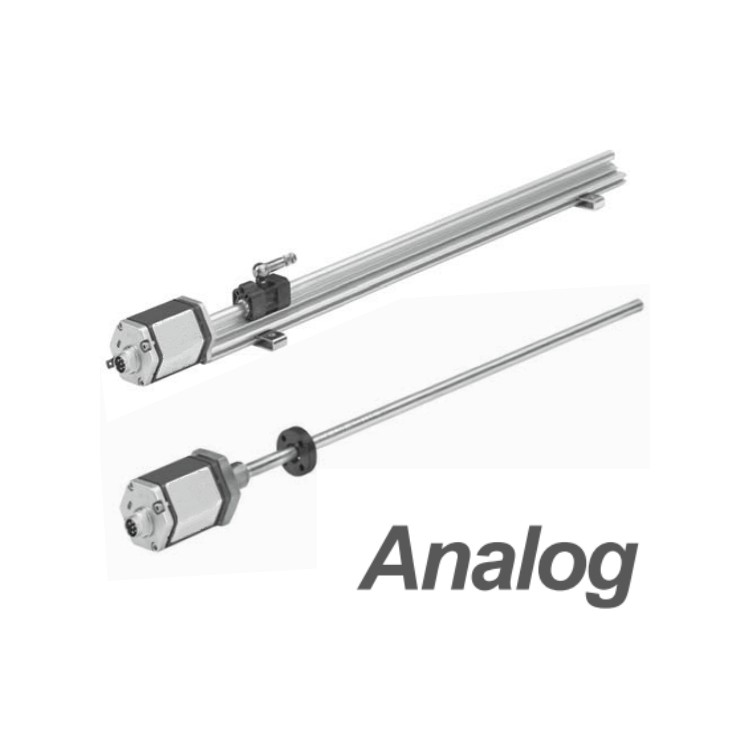


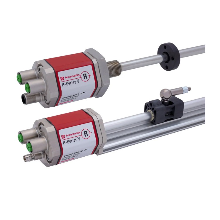
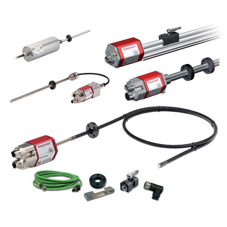


Robust and Reliable Industrial Displacement Sensors
■ Linear measurement, output
LED Indicator Diagnostics Function
■ Contactless measurement, no wear and tear
■ Non-linearity to 0.01%
■ Repeat accuracy up to 0.001%
Simulated Output, Position and Speed
Adjustable zero point and full scale
| Parameters | Specs |
| Input | |
| Measurement Data | Location, speed |
| Measurement Range | RP Aluminum Molding Shell: 50 - 5080 mm; RH Pressure-resistant Outer Tube: 50 - 7620 mm |
| Output | |
| Voltage | 0 ~ 10 Vdc, 10 ~ 0 Vdc, -10 ~ +10 Vdc, +10 ~ -10 Vdc (Controller Low Load: > 5k ohms) |
| Current | 4 ~ 20 mA or 20 ~ 4 mA (Low/High Load: 0/500 Ohms) |
| Accuracy | |
| Resolution | 16 D/A, 0.0015% (one part per million) |
| Non-linearity | Full scale soil 0.01% (Fine soil 50 pm) |
| Repeating Accuracy | ± 0.001% full scale (± 2.5 pm small) |
| Update Time | 0.5 ms (Stroke <1200 mm) / 1.0 ms (Stroke <2400 mm) / 2.0 ms (Stroke <4800 mm) / 5.0 ms (Stroke <7620 mm) |
| Temperature coefficient | < 30 ppm / °C |
| Working Conditions | |
| Magnet Speed | At your service |
| Operating Temperature | - 40 to +75 °C |
| Humidity / Dew Point | Humidity 90%, no condensation allowed |
| Protect | RP Aluminum Molding Shell: IP65 Pressure-resistant Outer Tube: IP67 (Connector must be securely locked) or IP68 (Optional with straight-out cable) |
| Impact Index | 100 g (Single Impact) / IEC Standard 68-2-27 |
| Oscillator Indicator | 15 g / 100 - 2000 Hz / IEC Standard 68-2-6 (Durability) |
| EMC Testing | Radiation EN 50081-1, Immunity EN 50082-2, EN 61000-4-2/3/4/6, Grade 3/4, Class A, CE Certified |
| Structure, Material | |
| Fault Indicator | Electronic head and tail caps with LED display |
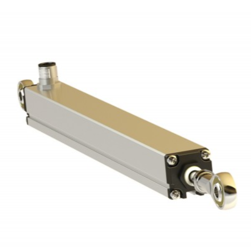
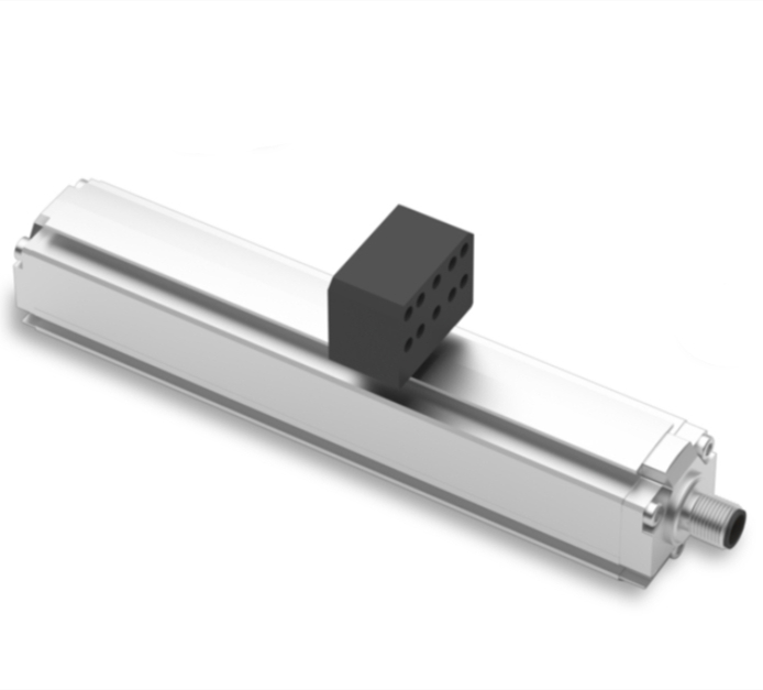
| RP Aluminum Molding Shell | Sensor Head: Aluminum, Sensor Rod: Aluminum, Position Magnet: Slider Magnet or Floating Magnet |
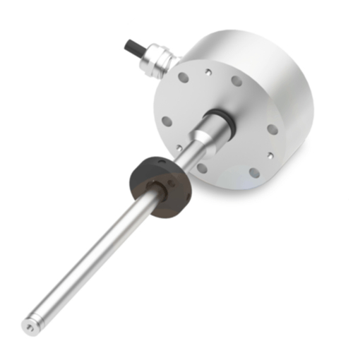
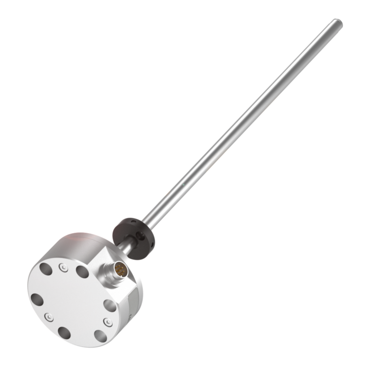
| RH Pressure-resistant Outer Tube | Sensor Head: Aluminum Sensor Rod and Flange: 304L Stainless Steel Outer Tube Pressure: 350 bar / 690 bar (Peak) Position Magnet: Ring Magnet, Floating Magnet, or Buoyant Ball |
| Installation | |
| Installation Location | Any direction |
| RP Aluminum Molding Shell | Detachable fixed clip (to be secured with M5 screws) |
| RH Pressure-resistant Outer Tube | Male threaded flange, Metric M18 x 1.5 or English 3/4"- 6 UNF-3A |
| Standard Locking Force | 45 N-m |
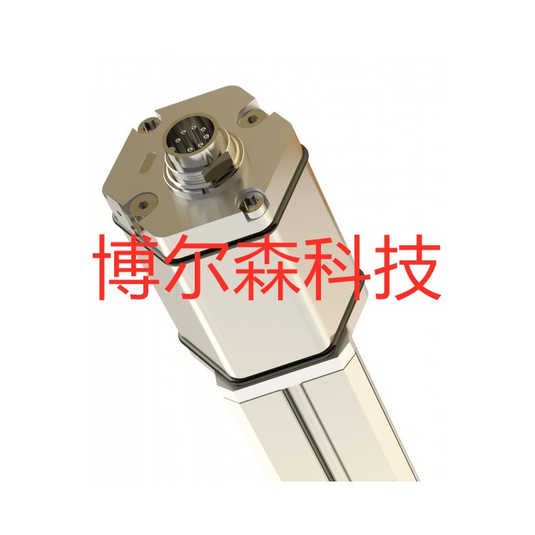
| Electrical Connections | |
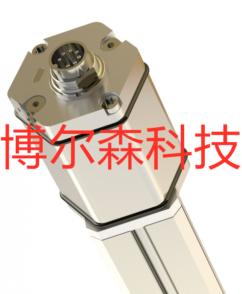
| Connector selection | 6 Pin D60 plug or straight cable |
| Input Voltage | +24 Vdc (-15 / +20%) |
| Polarity Protection | -30 Vdc |
| Overpressure Protection | 36 Vdc |
| Power consumption | Typically 100 mA or less |
| Fluctuation | < 1 % S-S |
| Electrical shock intensity | 500 V (DC ground wire to mechanical housing ground) |
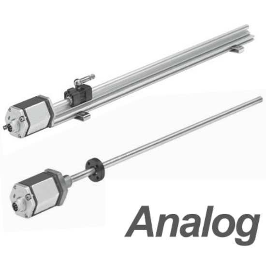
The R-Series analog outputs provide a set of outputs, represented as DC voltage or current. Due to the built-in 16-bit D/A converter in the sensor circuit, the output values are extremely fast. Additionally, since the position values are processed first within the sensor's internal electronic module, they can be directly output to the controller, thus eliminating the cost and computation time of an extra amplifier interface. By using the calculation software provided by BRSEN, users can easily adjust the sensor's zero point and full-scale range, please refer to the relevant programming data.
(Note: All BRSEN displacement sensors are factory-calibrated for zero and full-scale, so no re-adjustment is needed upon receipt. If any changes are required in the future, they must be made through programming tools such as calculator software, which must be purchased separately.)
The R-series offers DC voltages or currents, in either direction.
Note: Voltage or current output must be selected at the time of order; it cannot be changed on-site after shipment.

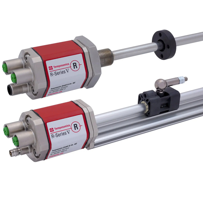
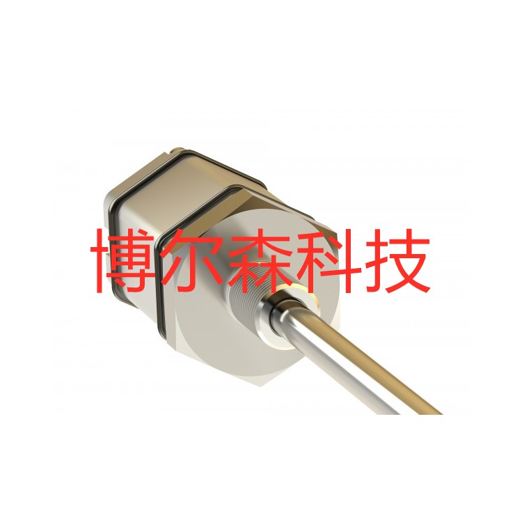
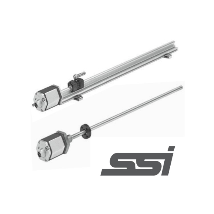
Pressure-resistant outer tube dimensions and installation instructions
RH series pressure-resistant outer tubes, aluminum profile electronic storage, designed specifically for hydraulic system use, internally mounted within the hydraulic cylinder, capable of withstanding pressure up to 34MPa continuously (69MPa peak). Available with thread specifications M18×1.5, M20×1.5, or 3/4”-16 UNF-3A.

Note: The upper and lower dead zones shown in the image indicate that the sensor's output is zero or unreliable within this area. The upper and lower dead zones for this sensor are 50.8 and 63.5mm, respectively. This value can be appropriately modified to meet customer requirements. Please specifically mention this to our sales or technical team when placing an order.
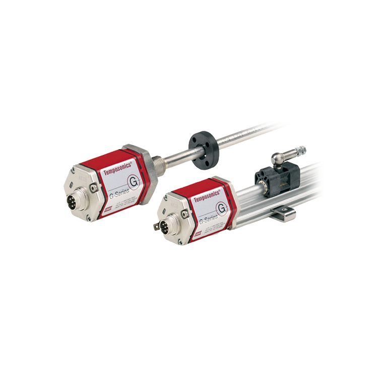
Aluminum Extrusion External Structure Dimensions and Installation Instructions
RP aluminum profile external mounting structure, suitable for general machinery, easy to install and maintain.

Sensor wiring method
When mating航空插头, define by the pin and corresponding wire color.
Waterproof connector directly exiting with wire color definition
D60 Connector Pin Arrangement (Facing the Sensor Head)

| Needle size | Line color | Definition |
| 1 | Ash gray | Analog Signal Output |
| 2 | Powder | Signal Ground |
| 3 | Yellow | Communication Interface (+) |
| 4 | Green | Communication Interface (--) |
| 5 | Brown | +24VDC(-15%/+20%) |
| 6 | White | Direct Current Power Supply接地 |