


I. Overview:
Rock triaxial tester applicable test methods standards: SL264-2001 "Rock Test Code for Hydropower and Water Conservancy Projects", GB/T 50266-2013 ≤Engineering Rock Mass Test Methods Standard≥, GB/T 23561.9-2009 ≤Methods for Determining Physical and Mechanical Properties of Coal and Rock≥. Developed based on national standards and related specifications, emphasizing practicality in the industry, simple operation, and precise data.
II. Key Features:
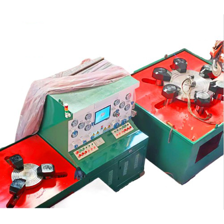
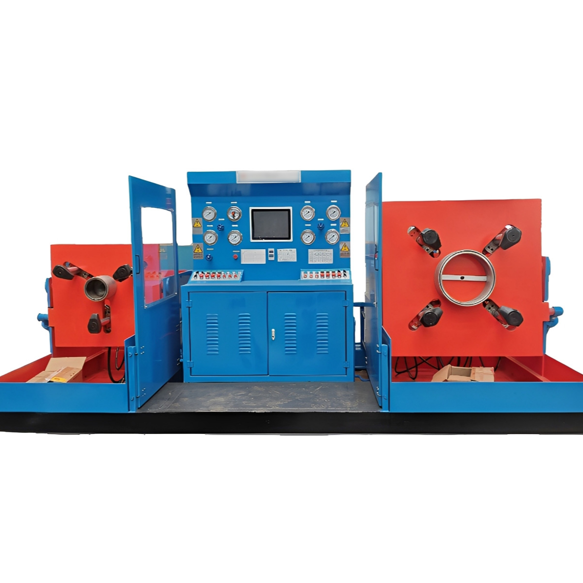
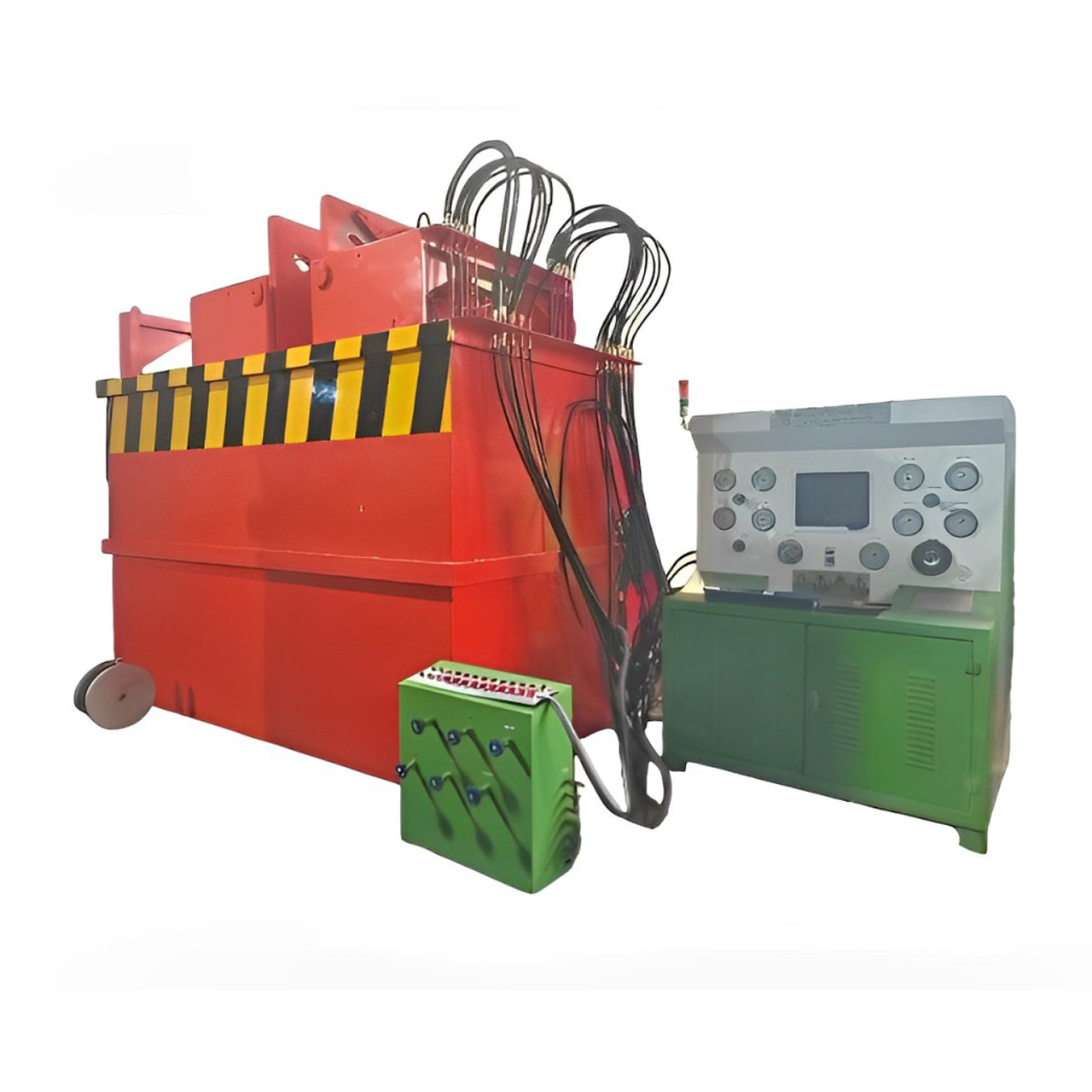
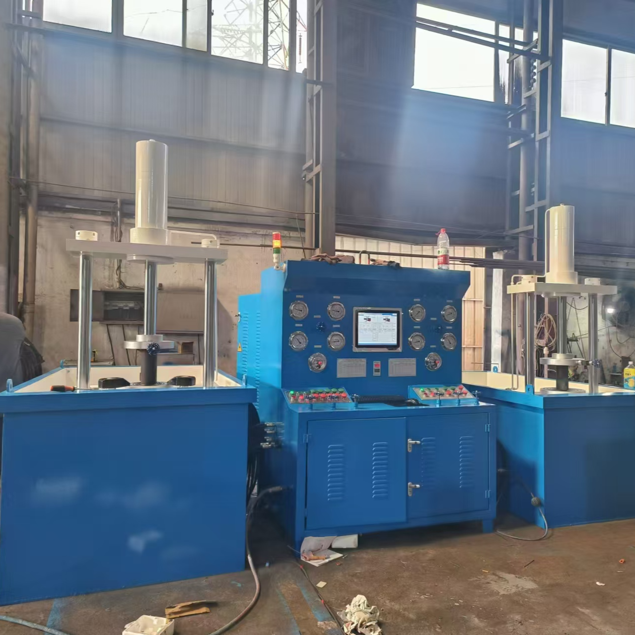
The tri-axial rock tester is mainly composed of a high-stiffness main unit, a pressure self-balancing tri-axial pressure chamber, an booster, a servo hydraulic power unit, servo valves, an air compressor unit, a measurement and control system, and a computer system.
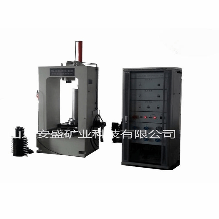
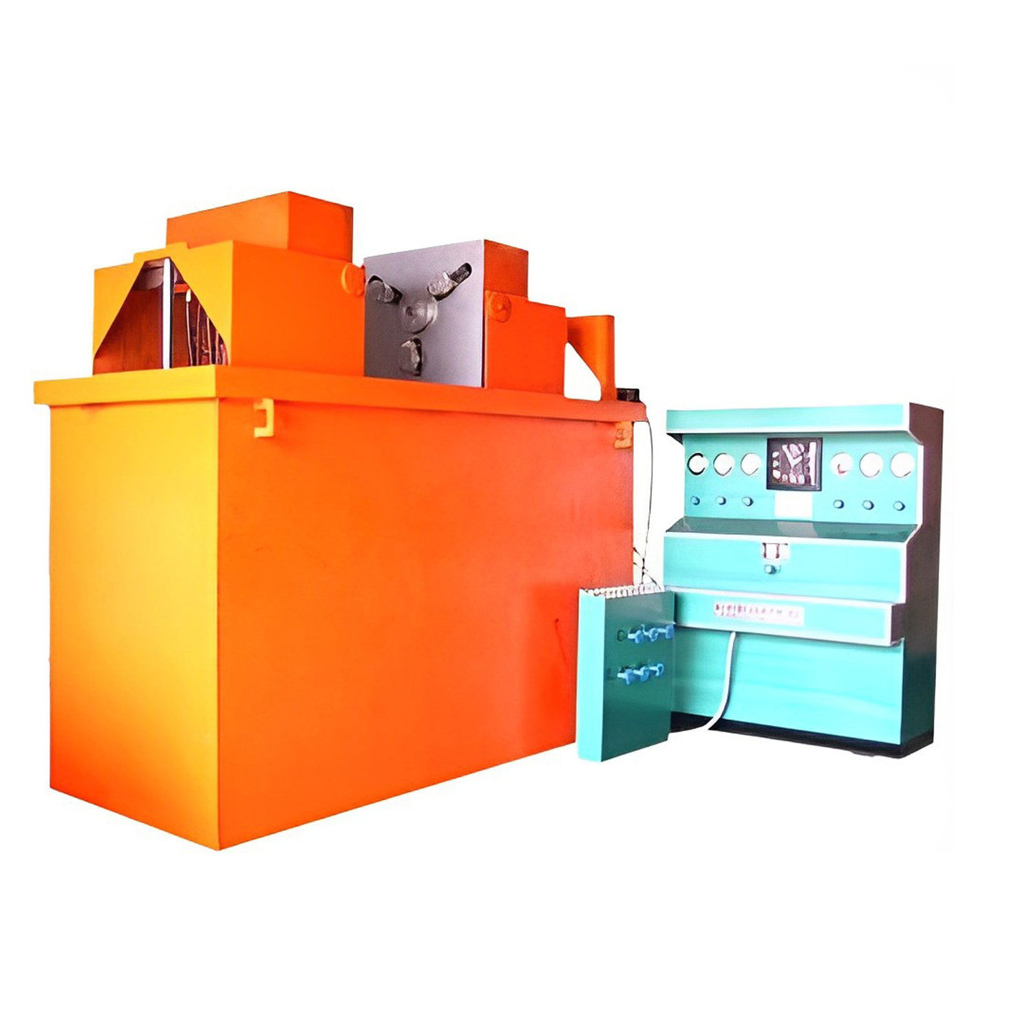
1. The high rigidity main frame features a door-type frame structure with high rigidity. The working cylinder is placed in the center of the bottom beam of the frame, with tracks on both sides for easy installation and removal of the three-axis pressure chamber. A spherical pressure plate is mounted in the center of the top beam of the frame, which can automatically align itself, ensuring a tight contact between the plate and the end of the compression rod.
2. The pressure self-balancing three-axis pressure chamber employs pressure self-balancing technology. Made from high-strength alloy structural steel, the pressure disks and pressure transfer piston rods are heat treated and precision-machined from bearing steel. The pressure chamber is mounted on a mobile trolley, allowing for easy movement along the track and convenient sample loading/unloading.
3. A booster is an ultra-high-pressure oil source that outputs after the system's working oil fluid is pressure-amplified, supplying the ultra-high-pressure oil fluid to the three-axis pressure chamber. It acts as the lateral pressure (i.e., confining pressure).
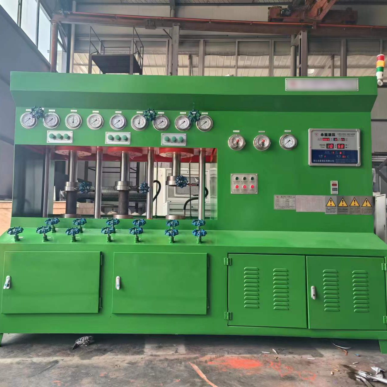
4. Servo hydraulic power source is a combination of parts, including a high-pressure plunger pump assembly, overflow valve, precise oil filter, temperature sensor, cooler, and a servo oil circuit system along with a surrounding pressure boosting system.
5. Drain assembly, for removing media from the pressure chamber.
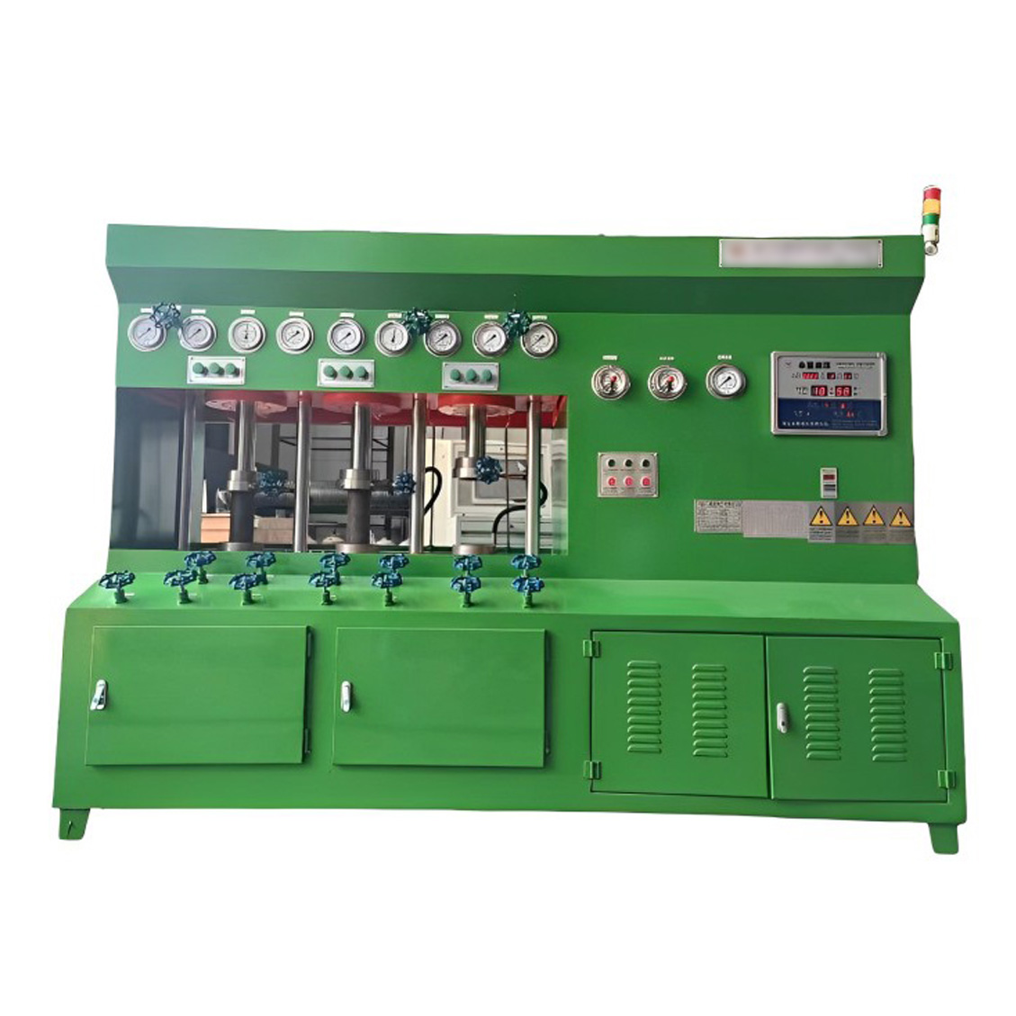
6. The measurement control system of the microcomputer-controlled electro-hydraulic servo triaxial rock tester consists of components such as axial force sensors, confining pressure sensors, axial deformation sensors, radial deformation sensors, displacement sensors, all-digital measurement controllers, and servo valves.
6.1 Equipped with 12 measurement channels, including 2 force channels, 1 axial deformation channel, 1 radial deformation channel, and 2 displacement channels.
6.2 High measurement resolution, varies throughout the full range without stepped increments.
6.3 Features automatic zeroing, calibration, and automatic storage functions.
6.4 Features constant test force, constant deformation, constant displacement, uniform test force rate, and uniform deformation rate control functions.
6.5 Features protection functions for overloading, over-range, oil circuit blockage, excessive oil temperature, and specimen breakage.
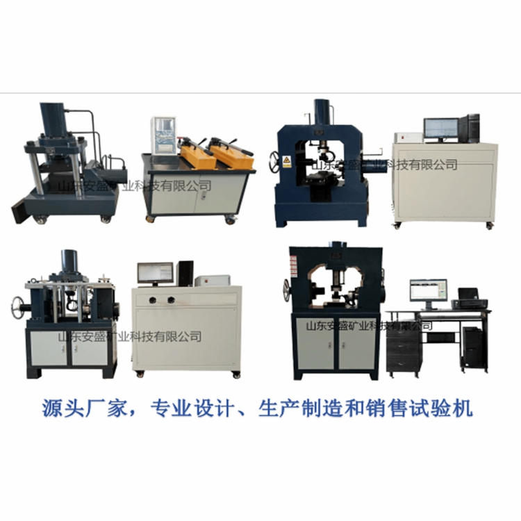
Section 3: Standard System Configuration:
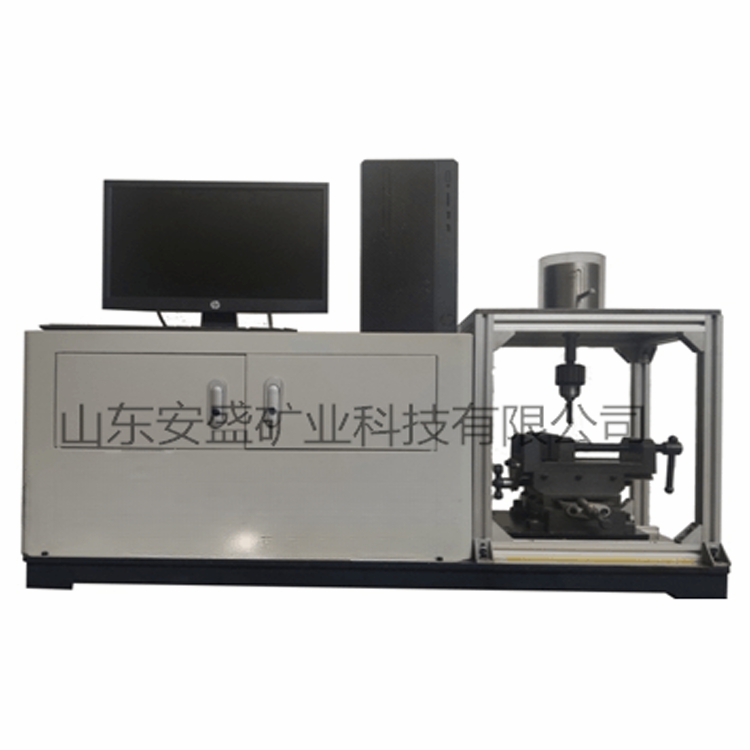
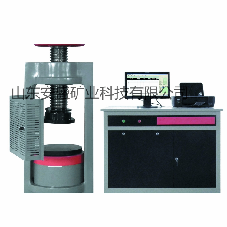
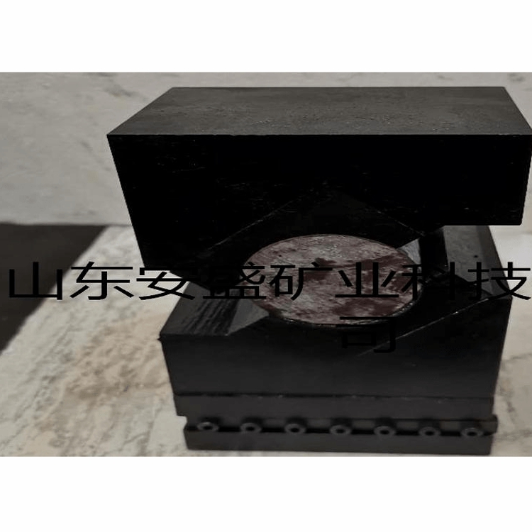
1. Rigid Main Unit, one unit (structure and rigidity as per customer's requirements), the current image shows the standard configuration.
2. Pressure Self-Balancing Three-Axis Pressure Chamber - 1 Unit
3. Booster set
4. Servo hydraulic power unit - one set
5. All-Digital Servo Controller - 1 Unit
6. Oil Separator Assembly Set
1 computer
IV. Main Technical Parameters:
1. The mainframe stiffness exceeds 6 GN/m
2. Axial test force of 1000 kN, force resolution of 10 N, and force accuracy ±1%.
3. Shear pressure of 60 Mpa, control accuracy of ±2% for shear pressure, and resolution of 0.01 Mpa.
4. Deformation measurement range: Axial 0-8mm, Radial 0-4mm, Measurement resolution 0.0001mm, Measurement accuracy ±1%
5. Displacement Control Range: 0-100mm, Measurement Accuracy < ±0.5%FS, Measurement Resolution Over 1/10,000
6. Waveform Control: Users can freely set various program waveforms containing loading, holding, and unloading phases (self-programmed) as needed. Future upgrades and feature additions are convenient, requiring the software to have independent intellectual property rights. The software copyright number is: Copyright Registration No. 4019370.
7. Extreme Control: Automatic protection is triggered when parameters such as axial deformation, radial deformation, and time reach their limit values or pre-sets, upon sample breakage, oil path blockage, or excessive oil temperature.
8. Space Height: 850mm, Width: 400mm (easily accommodates a Brazilian splitting fixture, three-axis chamber)
Specimen Size: Φ50x100mm。
10. Host Machine Dimensions: 800*1500*2300mm
11. Oil Source Dimensions: 2500*1100*500mm
12. Control cabinet footprint dimensions: 700*700*2000mm
13. Weight (approx.): 5100KG
14. Expandable for tests such as pore water pressure, high and low temperature environments, and rock creep.