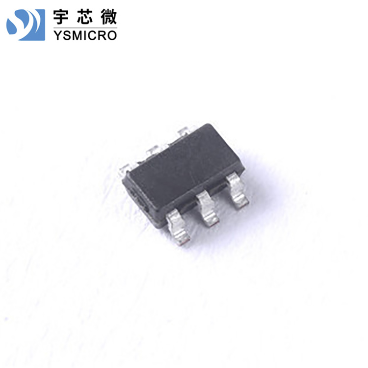


Darlington Driver Circuit ULN2202A Chip Description:
The ULN2202A is a monolithic integrated high-voltage, high-current Darlington array, featuring two independent Darlington driver channels within the circuit. It includes a flyback diode internally designed for driving inductive loads such as relays, stepper motors, etc. Each Darlington transistor collector can output up to 500mA current. Parallel connection of Darlington transistors achieves higher output current capability. This circuit is widely applicable in relay driving, lighting driving, display driving (LED), stepper motor driving, and logic buffers.
Each Darlington transistor in the ULN2202A is串联 with a 2.7K base resistor, and can be directly connected to TTL/CMOS circuits under a 5V operating voltage, allowing direct handling of data that previously required standard logic buffers.
Dalintronics Drive Circuit ULN2202A Features:
500mA Collector Output Current (Single Channel)
High Voltage Tolerance (50V)
Input compatible with TTL/COMS logic signals
Widely used in relay drives
Darlington Driver Circuit ULN2202A's Limiting Parameters:
TA25°C, unless otherwise specified
| Parameters | Symbol | Please provide the Chinese content you would like to have translated into American English. | Unit |
| Collector-Emitter Voltage (pins 4~5) | VCE | -0.5~50 | V |
| COM terminal voltage (pin 6) | VCOM | 50 | V |
| Input Voltage (Pin 1, 3) | VI | -0.5~30 | V |
| Collector Peak Current | ICP | 500 | mA/ch |
| Output clamp diode forward peak current | IOK | 500 | mA |
| Total Emitter Peak Current (Max) | IET | -2.5 | A |
| Operating Temperature (Max) | TJ | 150 | ℃ |
| Welding Temperature | 260 | ℃,10S | |
| Storage temperature range | Tstg | -60~+150 | ℃ |
| Power Consumption(1)(2) | PD | 0.57 | W |
Note: 1. Maximum power consumption can be calculated according to the following relationship:
PD=(TJ-TA)/θJA
2. TJ(max) is 150℃,TAAmbient Temperature for Circuit Operation
Darlington driver circuit ULN2202A electrical characteristics:
TA=25°C, unless otherwise specified
| Symbol | Parameters | Test Conditions | Minimum Value | Typical Value | zuiLarge value | Unit |
| VI(ON) | Conductive State Input Voltage | IC=200mA | 1.9 | 2.4 | V | |
| IC=250mA | 2 | 2.7 | ||||
| IC=300mA | 2.1 | 3 | ||||
| VCE(SAT) | Collector-Emitter Saturation Voltage Drop | VI=2.4V,IC=30mA | 0.78 | V | ||
| VI=2.4V,IC=60mA | 0.82 | |||||
| VI=2.4V,IC=120mA | 0.9 | |||||
| VI=2.4V,IC=240mA | 1.1 | |||||
| VI=2.4V,IC=350mA | 1.25 | |||||
| VF | Diode Forward Voltage Drop at Clamp Position | IF=350mA | 1.4 | 1.6 | V | |
| ICEX | Collector Turn-off Leakage Current | VCE=50V,II=0 | 50 | μA | ||
| VCE=50V,TA=85℃,VI=0V | 100 | |||||
| II | Input Current | VIN=12V | 4 | mA | ||
| VIN=6V | 1.7 | |||||
| VIN=4.5V | 1.1 | |||||
| VIN=2.4V | 0.35 | |||||
| IR | Clamping diode reverse current | VR=50V | 100 | μA | ||
| CIN | Input Capacitor | 15 | pF | |||
| tPLH | Transmission Latency: Low to High | VL=12V,RL=45Ω | 0.15 | 1 | μS | |
| tPHL | Transmission Latency: High to Low | VL=12V,RL=45Ω | 0.15 | 1 | μS |