


I. Usage and Features
ZZYP Type Self-Regulating PressureAdjustable ValveAn actuator product that achieves automatic regulation without any external energy source, utilizing the energy of the adjusted medium itself. This product features operation in environments without electricity or gas, while also saving energy. The pressure setpoint can be adjusted freely during operation. With quick-open flow characteristics, it operates sensitively and has good sealing performance, thus widely used in various industrial equipment across industries such as oil, chemicals, electricity, metallurgy, food, light industry, textile, mechanical manufacturing, and residential building complexes for automatic control of pressure reduction, stabilization (used for post-valve regulation), or pressure relief, stabilization (used for pre-valve regulation) of gas, liquid, and steam mediums.
II. Structure and Principle of Operation
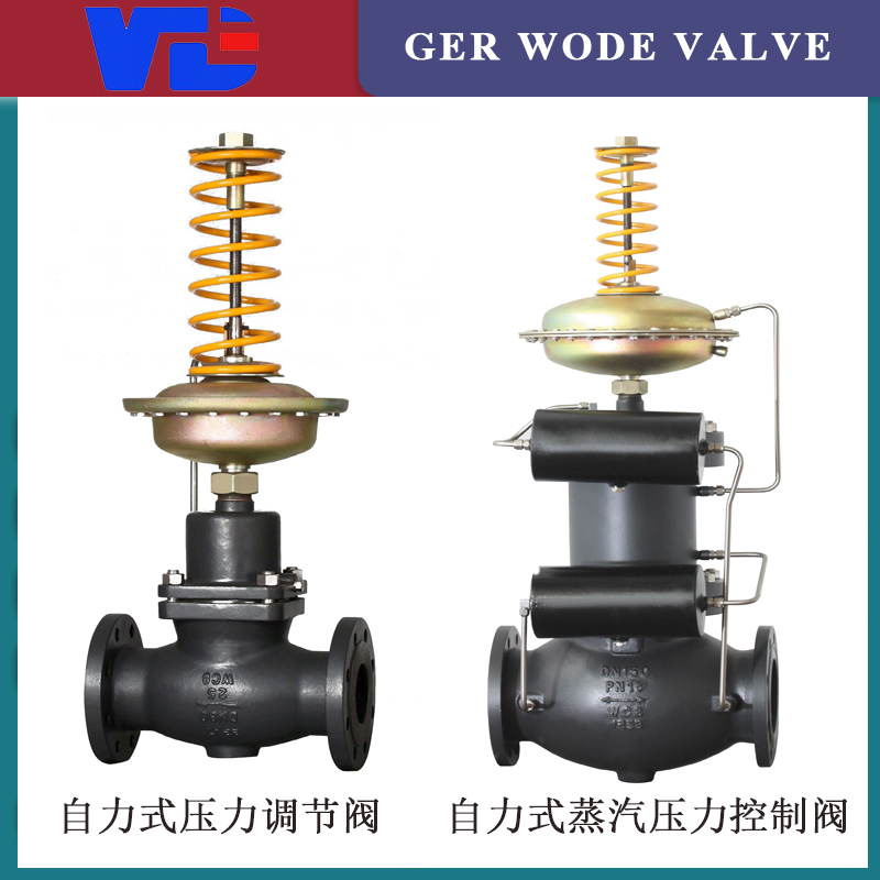
The pressure reducing valve consists mainly of four parts: the detection and actuating mechanism, the pressure reducing valve, the condenser, and the horizontal section of pipe after the valve (as shown in Figure 1).
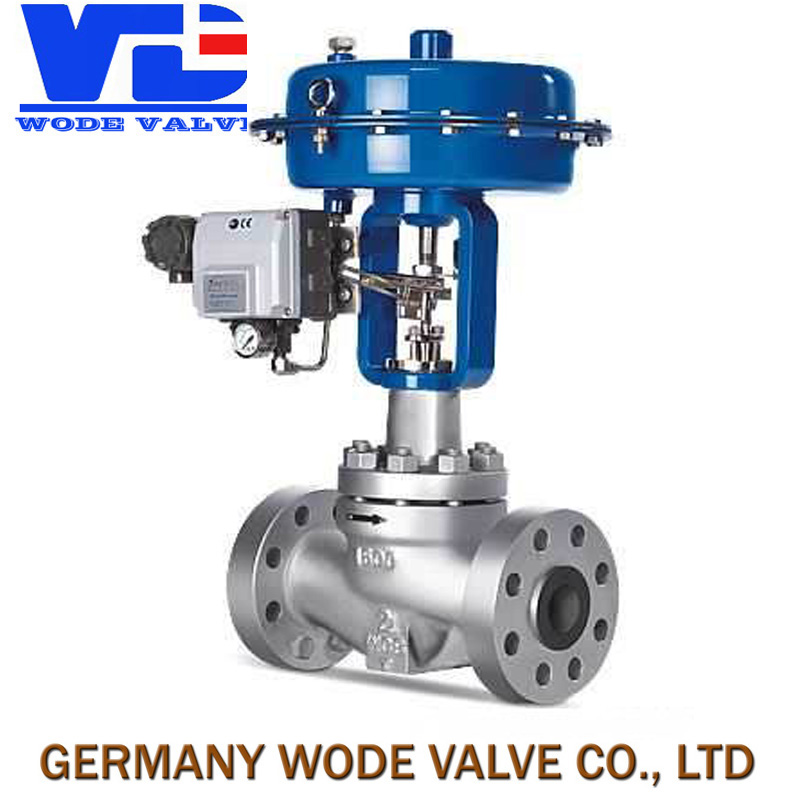
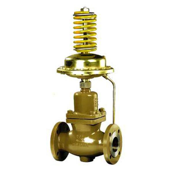
Figure 1a: Pressure-reducing valve used to control the downstream pressure of a valve, which operates in a shut-off type. The principle is as follows: The medium flows into the valve body in the direction of the arrow, passes through the valve core and seat to throttle, and then exits. Another path, after cooling through a condenser (used when the medium is steam), is introduced into the actuator to act on the diaphragm, causing the valve core to move correspondingly, achieving the purpose of pressure reduction and stabilization. If the downstream pressure increases, the force acting on the diaphragm increases, compressing the spring, which drives the valve core, reducing the valve opening until the downstream pressure drops to the set value. Similarly, if the downstream pressure decreases, the force on the diaphragm decreases, and due to the spring's reaction force, the valve core is driven, increasing the valve opening until the downstream pressure rises to the set value.
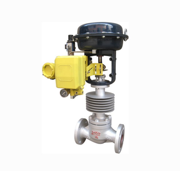
Figure 1b: Pressure regulating valve used to control the pressure before the valve, with a pressure-actuated operation. The principle is as follows: the medium flows into the valve body in the direction of the arrow, and another path is cooled by a condenser (used when the medium is steam) before being introduced to the actuator, which exerts force on the diaphragm. This causes the valve core to move correspondingly, achieving pressure relief and stabilization. If the pressure before the valve increases, the force on the diaphragm increases, compressing the spring and moving the adjusting core, which increases the valve opening until the pressure before the valve drops to the set value. Similarly, if the valve opening decreases, the pressure before the valve rises until it reaches the set value.


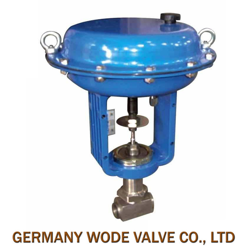
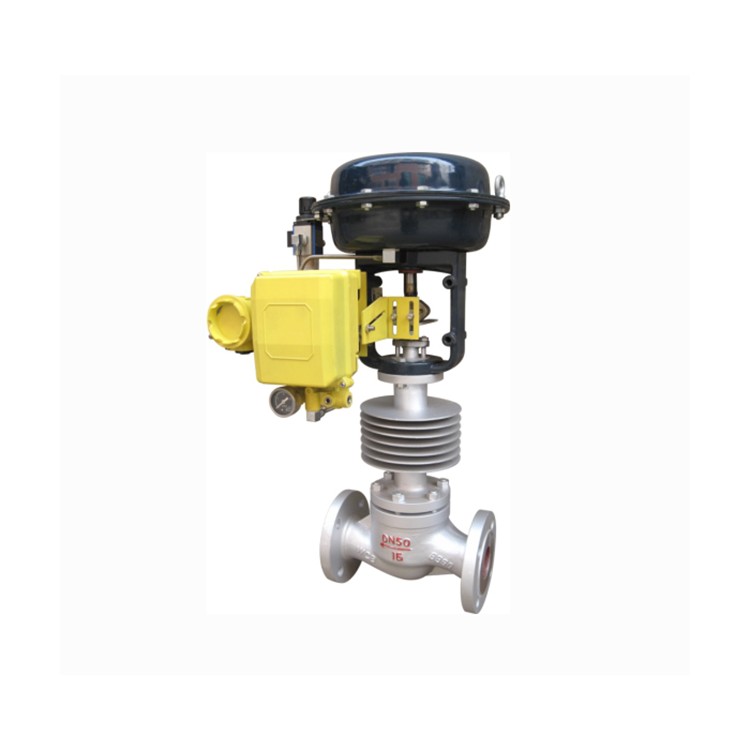
Figure 1b: ZZYP-16K Self-Operated Pressure Regulating Valve
1. Inlet Fitting 2. Exhaust Pipe 3. Detection Mechanism 4. Inlet Tube 5. Pressure Cover Screw
6. Condenser 7. Spring 8. Valve Stem 9. Valve Core 10. Bellows Tube
11. Pressure Regulating Disc 12. Filling Port Screw 13. Pressure Extraction Tube 14. Valve Inlet Pipe
15. Valve Seat 16. Valve Body
III. Main Technical Parameters and Performance Indicators, Materials
1. Key Technical Parameters and Performance Indicators

2. Pressure Adjustment Range Determined
Pressure adjustment range is segmented; see the table of main parameters and performance indicators. The control pressure should be selected as close to the middle value of the adjustment range as possible (refer to Table 1).
3. Pressure regulating valve after the valve, the relationship between the pressure before the valve and the pressure after the valve
The self-regulating valve is itself a regulating system, and the valve itself has specified pressure drop requirements. For the downstream pressure regulating valve (Type B), to ensure the downstream pressure remains within the specified range, the upstream pressure must reach the specified value. The requirements can be referred to in Table 2.
Table II

4. Dimensions and Weight

Valve core structure type

Valve body operating temperature and allowable pressure

4. Installation, Operation, and Maintenance
Installation; valves are used for gas or low-viscosity liquid media at normal temperatures (≤80℃), at this time...Pneumatic Diaphragm Control ValveSimilarly, they are vertically mounted on horizontal pipelines, as shown in Figure 3.

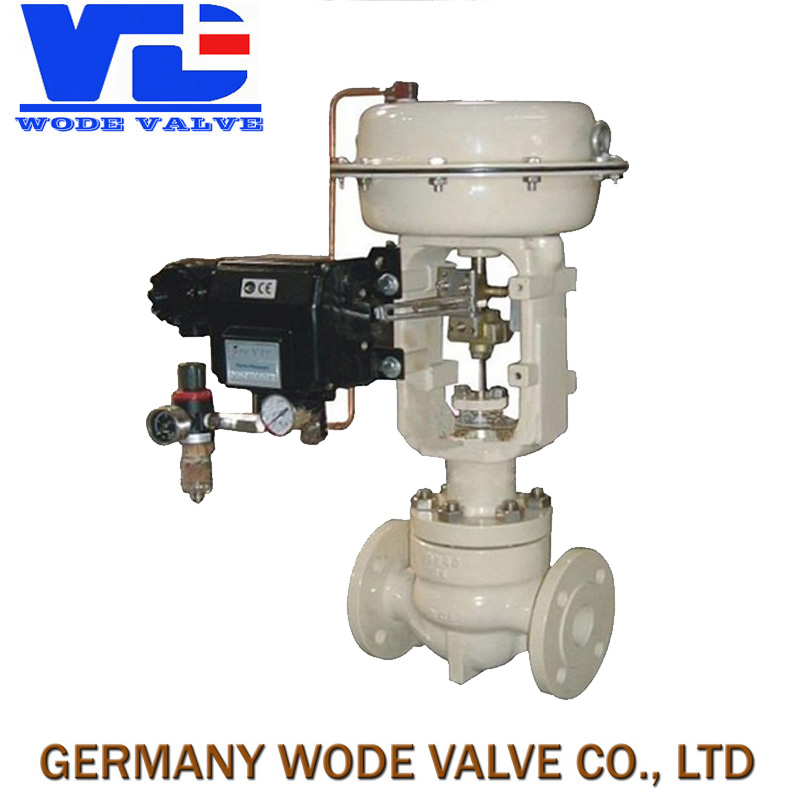
ZZYP-16B Self-Regulating Pressure Control Valve
1. Stop valve 2. Pressure gauge 3. Filter 4. Self-contained pressure regulating valve 5. Pressure gauge

b、ZZYP-16K Self-Regulating Pressure Control Valve
Figure 3: Installation for gases or low-viscosity liquids
If the medium used is steam, the self-contained pressure regulating valve must be installed in an inverted position on the horizontal pipeline, as shown in Figure 4.

a、ZZYP-16B Pressure Regulating Valve

1. Shut-off Valve
2. Pressure Gauge
3. Filter
4. Condenser
5. Pressure Regulator Valve
Figure 4: Installation when the medium is steam
5. Please note the following points during installation:
The condenser must be higher than the actuator of the pressure-reducing valve and lower than the downstream (downstream pressure-reducing valve) or upstream (upstream pressure-reducing valve) connection to ensure the condenser is filled with condensate.
(2) The pressure tapping should be located at an appropriate distance from the pressure-reducing valve. The pressure-reducing valve before should be greater than twice the pipe diameter, and the one after should be greater than six times the pipe diameter.
(3) For ease of on-site maintenance and operation, adequate space should be left around the pressure-reducing valve. A shut-off valve and a bypass manual valve should be installed before and after the valve, as shown in Figure 5.

Figure 5: Pressure Regulating Valve Assembly Installation Plan
Note: The dashed lines in the image represent another permitted direction for the pipe inlets and outlets.
(4) For pressure-reducing valves with an outlet size of DN≥100, a fixed bracket should be provided.
(5) The medium flow direction should align with the arrow on the valve body, and the center of the front and rear pipes should be aligned with the centers of the two flanges on the pressure-reducing valve to avoid excessive stress on the valve body.
(6) Filters should be installed before the valve to prevent impurities in the medium from causing blockages.
(7) The regulating valve should be installed in environments where the temperature does not exceed -25℃ to 55℃.
2. Utilize
Operation procedure for use with gases or low-viscosity liquids at room temperature: (refer to Figure 3)
(1) Slowly open the valve before and after the shutoff valve.
(2) Loosen the exhaust plug until gas or liquid overflows from the actuator.
(3) Then, retighten the exhaust plug, and the pressure regulator will function. The required pressure value can be adjusted through the pressure adjustment disk. When adjusting, pay attention to the pressure indicator, and make the movement slow and avoid turning the valve stem.
Operation procedure for steam applications (refer to Figure 4)
Remove the screw from the liquid injection port on the condenser.
(2) Remove the exhaust plug of the桦wrench actuator.
(3) Add water through the injection port until steam exits from the exhaust port using a nozzle.
(4) Tighten the exhaust plug and continue to fill with water until it overflows from the filling port.
(5) Tighten the liquid filling port screw.
(6) Slowly open the throttle valve and the shut-off valve before and after.
(7) Adjust the pressure regulator and observe the pressure indicator until it reaches the required value.
3. Maintenance
The regulating valve, once in operation, typically requires minimal maintenance effort. Routine checks should simply verify that the pressure readings before and after the valve align with the process requirements.
The required values are sufficient. Additionally, inspect for any leakage in the stuffing box and the actuator; if leakage is detected, tighten or replace the packing and diaphragm as needed.
Common Fault Exclusion Methods for Pressure Reducing Valves (see Table 5)

V. Ordering Instructions
Please provide the following information when placing an order: