


Abstract
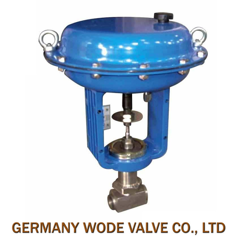
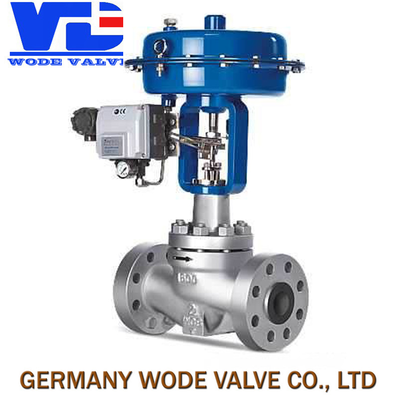
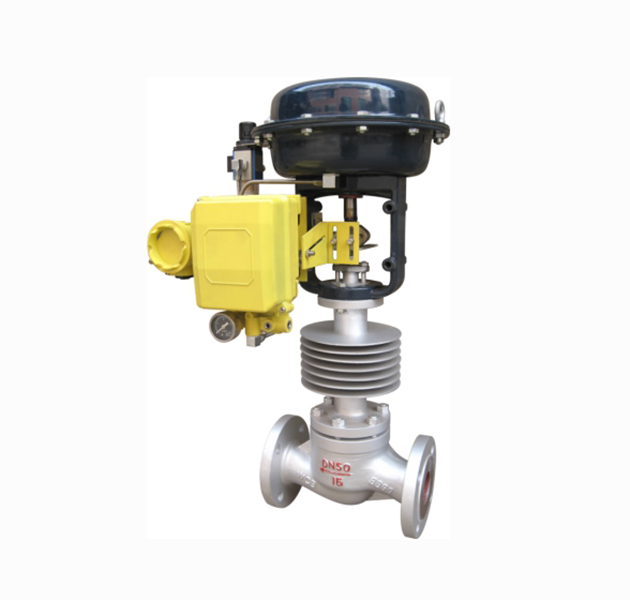
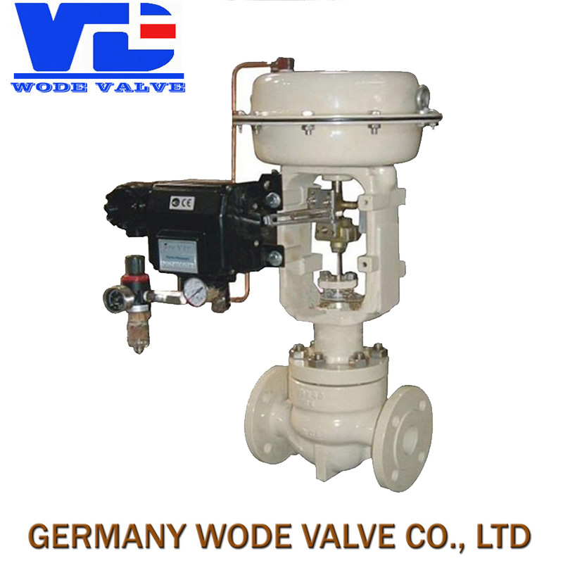
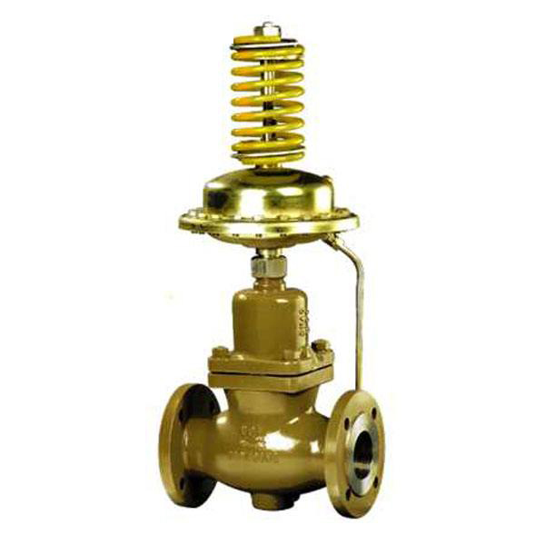
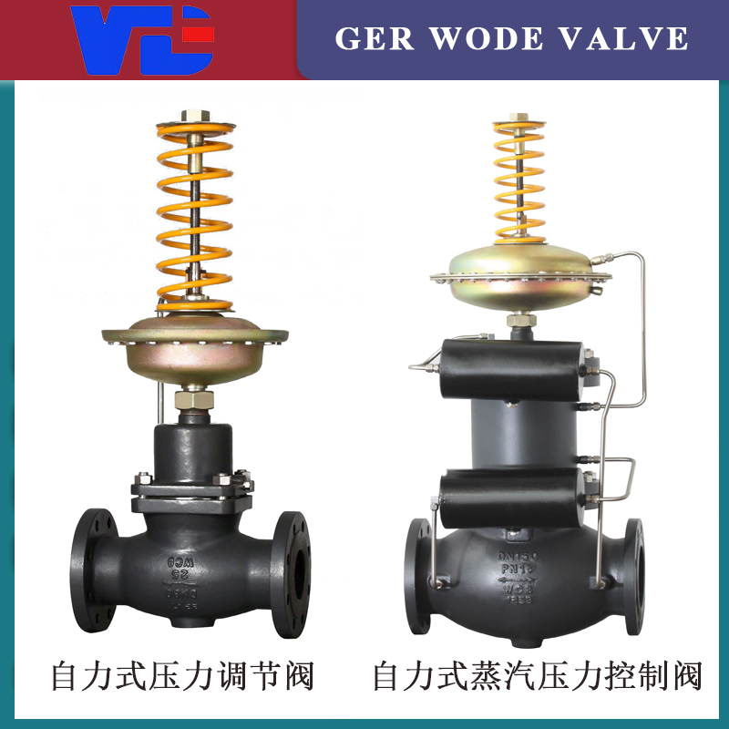
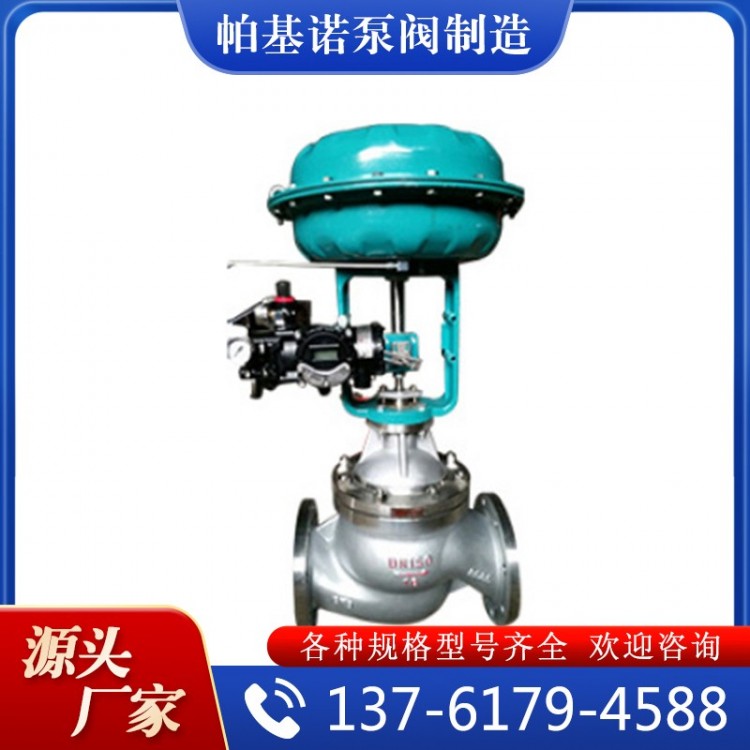
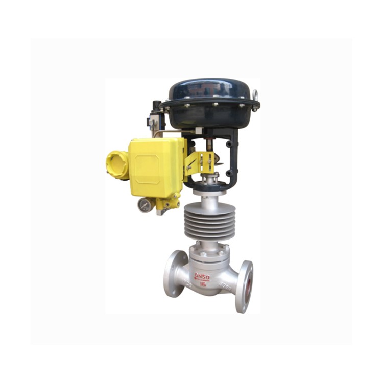
The PJZJP Miniature气动Film Single Seat Control Valve utilizes a top-guided structure and is equipped with a multi-spring actuator. It boasts compact design, lightweight, sensitive operation, S-shaped streamlined fluid passage, low pressure drop loss, large valve capacity, flow characteristics, and easy assembly and disassembly.
Product Introduction
I. Overview
PJZJP Miniature PrecisionPneumatic Diaphragm Single Seat Control ValveUtilizing a top-guided structure with multi-spring actuators, featuring compact design, lightweight, sensitive operation, S-shaped streamlined fluid channels, low pressure drop, large valve capacity, precise flow characteristics, and easy assembly. Widely applied in precise control processes of gases, liquids, and other media, such as maintaining pressure, flow, and liquid level at set values. Particularly suitable for applications with minimal leakage and small pressure differences before and after the valve. The series includes standard, regulating-cut-off, bellows-sealed, and jacket-insulated types, among others. The nominal pressure ratings are PN16, 40, and 64; nominal pipe sizes range from DN20 to DN350. Suitable for liquid temperatures ranging from -200℃ to +560℃ across various grades. Leakage standards are available in IV or VI levels, with flow characteristics in linear or equal percentage.
Section 2: Main Component Materials
1. Valve body, valve cover: ZG230-450, ZG1Cr18Ni9Ti
2. Valve Core and Seat: 1Cr18Ni9Ti, Stellite alloy surfacing
3. Filling Materials: PTFE, flexible graphite, stainless steel bellows.
4. Soft Sealing Valve Core: Enhanced PTFE
5. Gaskets: Rubber asbestos board, 1Cr18Ni9Ti, asbestos-wound gaskets;
6. Film Cover: A3
7. Woven Membrane: Nitrile rubber reinforced with polyester fabric;
8. Spring: 60Si2Mn
9. Valve Rods, Push Rods: 2Cr13, 1Cr18Ni9Ti
10. Liner: 2Cr13.
Section 3: Main Technical Parameters
Nominal Pipe Size DN (mm) (Spool Diameter dn) | 20 | 25 | 40 | 50 | 65 | 80 | 100 | 125 | 150 | 200 | 250 | 300 | 350 | |||
| 20 | 25 | 32 | 40 | 50 | 65 | 80 | 100 | 125 | 150 | 200 | 250 | 300 | 350 | |||
| Rated flow coefficient Kv | Straight | 6.9 | 11 | 17.6 | 27.5 | 44 | 69 | 110 | 176 | 275 | 440 | 690 | 1100 | 1760 | 2200 | |
| Waiting percentage | 6.3 | 10 | 16 | 25 | 40 | 63 | 100 | 160 | 250 | 400 | 630 | 1000 | 1600 | 2000 | ||
| Rated Stroke (mm) | 16 | 25 | 40 | 60 | 100 | |||||||||||
| Effective Diaphragm Area Ae (cm²) | 350 | 350 | 600 | 1000 | 1600 | |||||||||||
| Signal Range Pr | 20~100、40~200(KPa) | |||||||||||||||
| Gas Source Pressure Ps | 0.14~0.4(KPa) | |||||||||||||||
| Intrinsic traffic characteristics | Straight, Equal Percentage | |||||||||||||||
| Inherent adjustable ratio | 50:1 | |||||||||||||||
| Permitted leakage amount | Rigid Valve Seat: Grade IV, Soft Valve Seat: Grade VI | |||||||||||||||
| Nominal Pressure PN | 1.6、4.0、6.4(MPa) | |||||||||||||||
| Operating Temperature t (℃) | Room Temperature Type | -20~200、-40~250、-60~250 | ||||||||||||||
| Cooling-type | -40~450、-60~450 | |||||||||||||||
| High-temperature type | 450~560 | |||||||||||||||
| Low-temperature type | -60~-100、-100~-200、-200~-250 | |||||||||||||||
IV. Main Technical Parameters of the Actuator
Model | ZHA/ZHB-22 | ZHA/ZHB-23 | ZHA/ZHB-34 | ZHA/ZHB-45 | ZHA/ZHB-56 |
| Effective Area Ae (cm²) | 350 | 350 | 560 | 900 | 1600 |
| Process mm | 16 | 25 | 40 | 60 | 100 |
| Spring Range Kpa | 20-100 (Standard); 40-200; 20-60; 60-100 | ||||
Figure 5: Outline and Dimensional Drawing

SixOuter dimensions
DN | L | H | H1 | Weight: Kg | ΦA | |||||||
| PN6/16 | PN40 | PN64 | Standard | High temperature | PN6 | PN16 | PN40 | PN64 | PN6/PN16 | PN40/64 | ||
| 20 | 184 | 197 | 210 | 410 | 560 | 50 | 57 | 70 | 20 | 24 | 285 | |
| 25 | 184 | 197 | 210 | 410 | 560 | 50 | 57 | 70 | 20 | 24 | ||
| 40 | 222 | 235 | 251 | 455 | 620 | 65 | 75 | 85 | 26 | 35 | ||
| 50 | 254 | 267 | 286 | 475 | 627 | 70 | 82 | 90 | 30 | 40 | ||
| 65 | 276 | 292 | 311 | 610 | 790 | 80 | 92 | 102 | 47 | 66 | 360 | |
| 80 | 298 | 317 | 337 | 622 | 8074 | 95 | 100 | 107 | 55 | 78 | ||
| 100 | 352 | 368 | 394 | 640 | 850 | 105 | 110 | 117 | 125 | 65 | 99 | |
| 150 | 451 | 473 | 508 | 870 | 1130 | 132 | 142 | 150 | 175 | 130 | 160 | 470 |
| 200 | 600 | 615 | 650 | 890 | 1150 | 160 | 170 | 187 | 207 | 175 | 250 | |
| 250 | 650 | 670 | 690 | 1203 | 1523 | 187 | 202 | 225 | 235 | 350 | 470 | 580 |
| 300 | 740 | 770 | 800 | 1234 | 1554 | 220 | 230 | 257 | 265 | 500 | 660 | |
| 350 | 830 | 850 | 880 | 1294 | 1614 | — | — | 285 | — | —— | —— | |
Section 7: Performance Specifications
Item | Index Value | Item | Index value | ||||
| Basic Error % | No GPS Tracker | ±5.0 | Always Point Deviation % | Air Valve | No GPS Tracker | Starting Point | ±5.0 |
| With locator | ±1.0 | End Point | ±2.5 | ||||
| Backlash % | No GPS Tracker | ≤3.0 | Tracker-equipped | Starting Point | ±1.0 | ||
| Tracker-equipped | ≤1.0 | End Point | ±1.0 | ||||
| Air valve | No GPS tracker | Starting Point | ±2.5 | ||||
| End Point | ±5.0 | ||||||
| Dead Zone % | Without a locator | ≤3.0 | Tracker-equipped | Origin | ±1.0 | ||
| End Point | ±1.0 | ||||||
| Tracker equipped | ≤0.4 | Permitted leakage: L/h | 0.002 x valve rated flow | ||||
| Rated travel deviation % | ±2.5 | ||||||
Section 8: Allowable Pressure Difference

For detailed information, please call or email for inquiries!