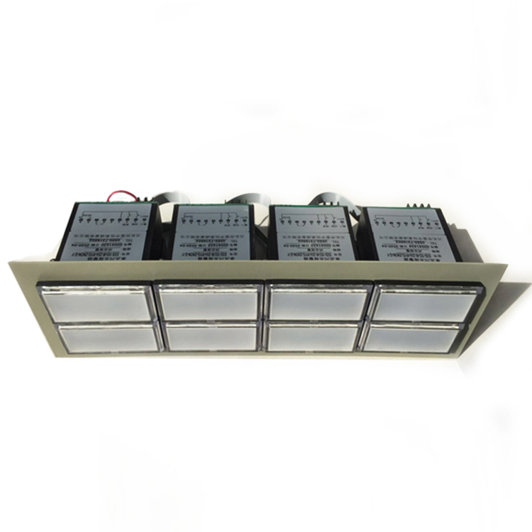


Flash alarm
Adopting an internal buzzer sound system and panel indicator flashing, as well as a passive contact output from the rear terminal, to achieve a three state alarm
Overview of Flash Alarm Devices
Introduction
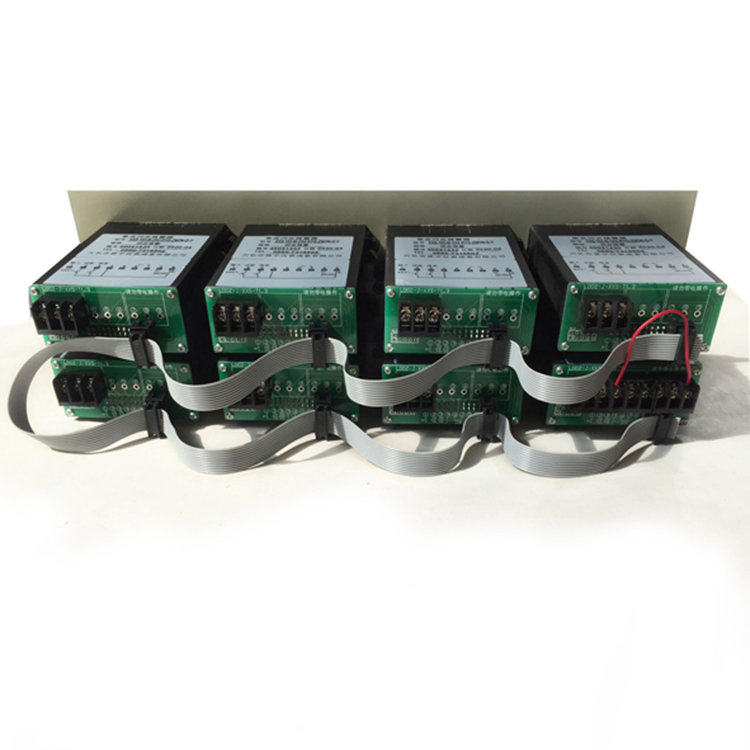
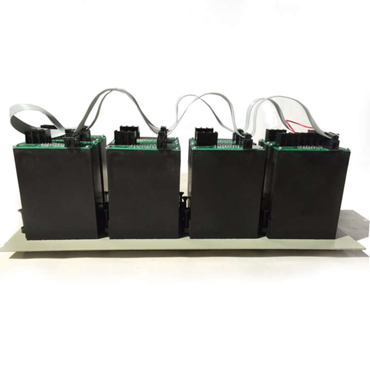
The intelligent flash alarm is composed of a small microcomputer detection system using the ATC51 series microcontroller, which replaces the traditional circuit that only uses hardware to implement alarm functions. This greatly reduces the number of components in the entire machine and improves reliability. The input circuit adopts a photoelectric isolator, which enables complete isolation between the CPU and external circuits. The multiple inputs are all normally open passive input methods. The alarm adopts an internal buzzer sound system, panel indicator flashing, and rear terminal output passive contact method to achieve a three state alarm. This series of instruments adopts a door entry without any components, with a reasonable structural design, superior performance, reliable operation, long service life, and easy maintenance, and is deeply trusted by a large number of users.
Scope of Application
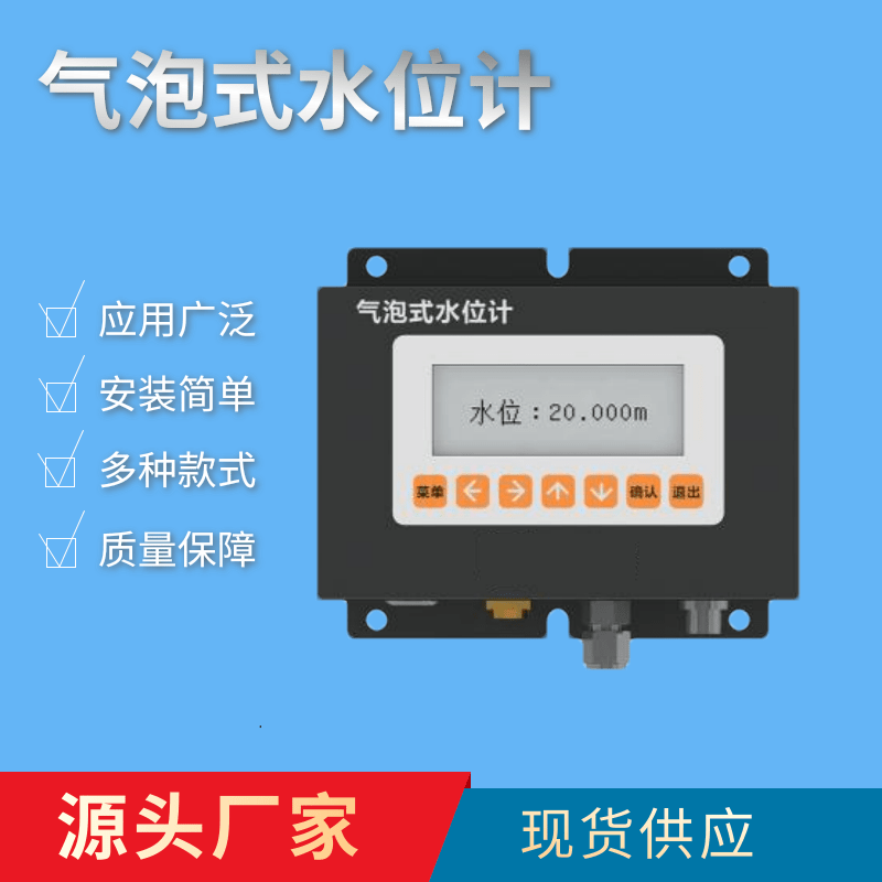
The flashing signal alarm is suitable for when a certain control parameter is exceeded, the corresponding circuit can emit an audible and visual alarm signal. It adopts high-performance microcontroller control, and the alarm window adopts LED flat panel display components. It has the characteristics of soft chromaticity and long-distance observation. When used in conjunction with various control and detection instruments with voltage switches or no voltage contact switches, it emits sound and light alarm signals and outputs alarm contacts when the parameters in the production process exceed the limit values, to attract the attention of operators and take measures. It is a cost-effective instrument that has been widely used in various industries for sound and light alarms when the process parameters exceed the limit.
Main technical indicators
Technical Specifications
Power supply voltage: AC200V ± 10% 50HZ or DC24V ± 10%
Input method: Passive contact, no additional input power allowed.
Relay contact output: AC 240V 3A DC28V 5A
The resistance of the circuit point is less than or equal to 30 ohms.
Power consumption: about 5W (eight circuits simultaneously in alarm state, excluding power of electric bell and buzzer)
Equipped with time display function
working principle
Multiple input signals are converted into high and low levels by a photoelectric isolator and enter the microcontroller. The microcontroller restores the sequence of high and low levels to corresponding state variables one by one, while emitting a three state alarm of sound and light contacts. It also has panel silencing and lamp testing functions.
Features
The instrument adopts high-performance microcontroller logic recognition technology, which is suitable for inputting various logic variables (passive contacts, TTL, OC gates and other signal types) and multiple input signal types; Can be equipped with OC gate signal output.
Design according to international standard procedures; It can also be made according to user requirements; Can be equipped with alarm memory function.
The instrument is equipped with a buzzer, test and mute buttons inside, and has interfaces for external communication (passive contact signals) and test and mute buttons.
The instrument adopts a card in structure design that is compatible with the domestically produced XXS series flash signal alarm, making it easy to install, maintain, and replace.
The instrument can be equipped with a serial communication interface output, and the transmission rate can be determined at the time of ordering. It can communicate bidirectionally with various devices with input/output communication functions and form a monitoring system.
Related models: XXS-10 XXS-103 XXS-103A XXS-103A4 XXS-103M