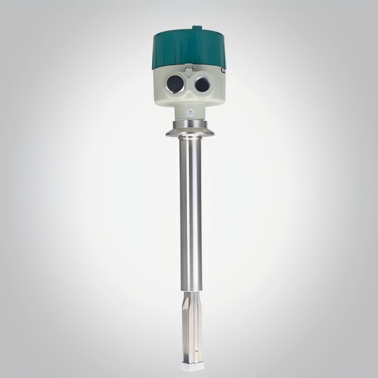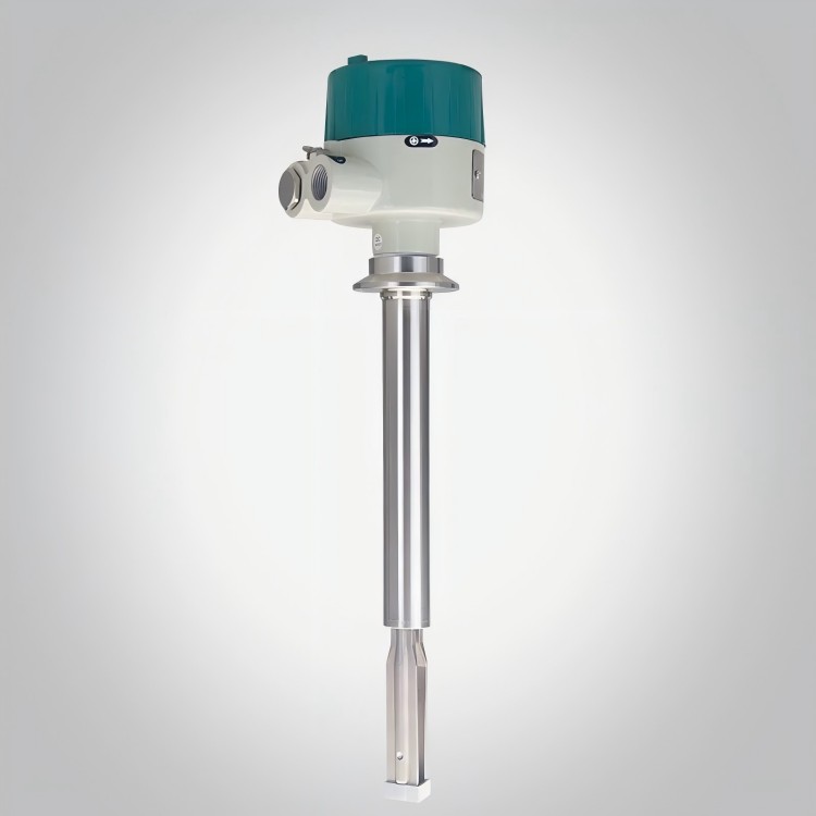


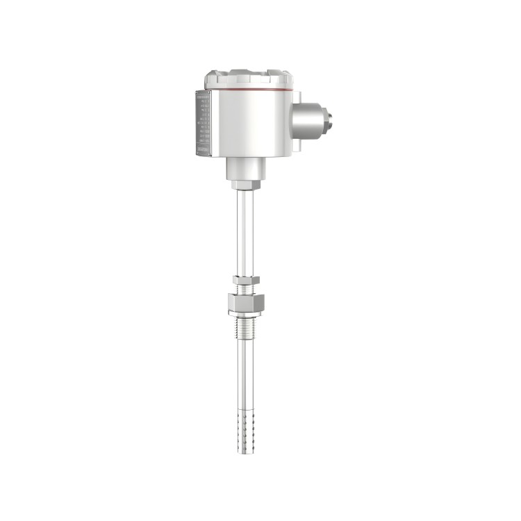
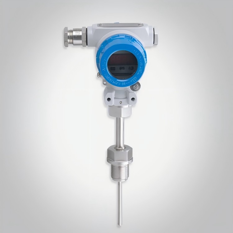

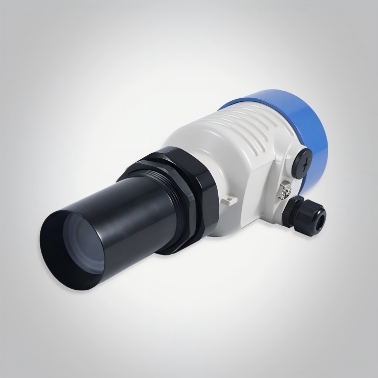
Tuning Fork Switch
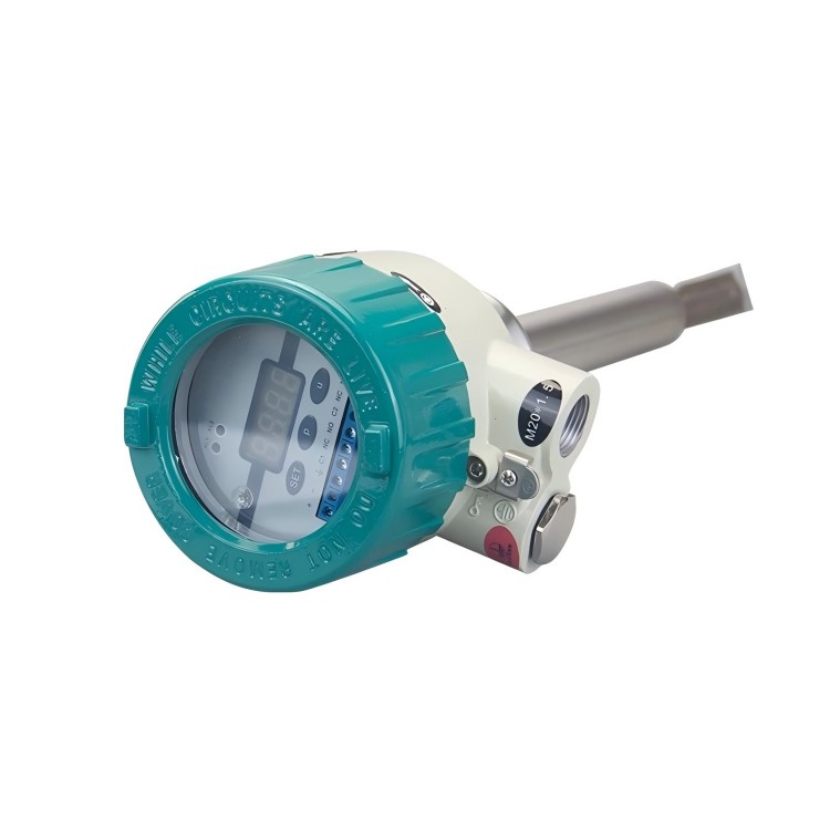


The SBYC series of reed switches are activated by the resonance of an electrocrystal, which causes them to vibrate. When subjected to material damping, the amplitude rapidly decreases and the frequency and phase undergo significant changes. These changes are detected by the internal electronic circuit, processed, and then converted into switch signals for output. The SBYC series reed level switches can monitor, control, and alarm for the high and low levels of material tanks, suitable for various liquids, powders, and granular solids. They are practical, simple to use, reliable in operation, highly adaptable, and require minimal maintenance. Both the reed and the output have operating states, indicated by LED lights, and the status indication can be adjusted according to preference. They come with three output types (DC 24V, AC 110V, and AC 220V) and various output options, including DC current output, relay contact output, and DC voltage output. All types have high or low fault alarm simulation and selectable instrument switch sensitivity.
SBYC Series Proximity Switch Technical Parameters:
Medium Temperature Range: -30℃ to 150℃
(2)Ambient Temperature: -20℃ to 80℃
(3)Ambient Humidity: ≤95%RH
(4)Tested Medium: Liquid, Powder, or Granular Solid
(5)Tested Medium Density: Solids ≥ 0.1 g/cm³; Liquids ≥ 0.7 g/cm³
(6)Tested Solid Particle Size: ≤10mm
(7) VeryBulk liquid viscosity: <1000 mm²/s
(8)Resting angle of medium under test: ≥200
(9)Pressure Range: ≤2 MPa
(10)Shell Material: Die-Cast Aluminum Alloy
(11)Fork Material: 1Cr18Ni9Ti 316 Stainless Steel
(12) Explosion-proof Class EXDIICT6
(13) Enclosure Protection Class: IP66
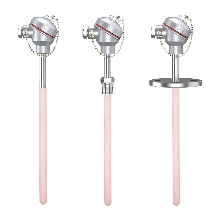
(14) Connection Type: 1"NPT Thread; Flange (Customer Selected)
(15) Electrical Parameters:
Supply Voltage: DC 24V; AC 220V 50Hz
② Output Signal: Relay Output: 8A 220V AC
(16) Fork Vibration Frequency: 300 ± 50 Hz
(17) Environmental Vibration Level: Acceleration not exceeding 1g at V.L.4
(18) Switch Signal Action Time: 1-60S
SBYC Series Proximity Switch Installation Method
1. The gauge is typically installed vertically, horizontally, or at an angle with the fork tip pointing down (it is recommended to install it vertically with the fork tip pointing down when the material has strong adhesion).
2. The instrument is not allowed to be installed in an inverted manner, i.e., with the fork end facing upwards.
3. It is recommended to use a vertical or inclined installation method when there are lumps or hard particles mixed in the material.
4. Before installing on the equipment, it is recommended to calibrate sensitivity with a small sample of the medium. For instance: immerse the instrument in a container filled with the medium to test the reliability of the switch.
5. During actual installation, it is typically categorized into top mounting (high-level monitoring of the medium), side wall mounting (high-level or low-level monitoring of the medium), and pipeline mounting (air flow monitoring for the material pump).
Tuning Fork Switch Precautions:
Prevent material bonding that could hinder the vibration of the gear fork.
2. In scarification situations, adequate space should be left between the toothed fork and the can wall.
3. Instruments for liquid level monitoring, with detection points determined based on the required height for surveillance or control.
4. For low-viscosity liquids, the tuning fork head can be freely separated from the process medium, allowing for installation at any position as shown in the above illustration.
5. For high-viscosity liquids, the tuning fork head cannot be freely separated from the process medium; it is recommended to install vertically with the fork tip pointing downwards.
6. Instruments for level monitoring, for vertical cylindrical containers or similar vessels, the installation position depends not only on the required height of material to be monitored or controlled but also on the angle of repose of the material and the feeding position. When horizontally installed, the fork end should be at a distance of one-third of the container's radius from the inner wall; the two prongs should be in the same horizontal plane. When vertically installed at the top of the container, the distance between the installation center and the container's inner wall should be one-third of the container's radius. The instrument's installation position should be avoided as much as possible from direct impact or splashing of the material flow to prevent false operation and wear. If the impact or splashing of the material cannot be avoided, a protective canopy can be installed above the instrument installation position, with an effective width greater than the fork end width and a length greater than the actual size of the instrument infiltrating into the material storage.
Warning! Do not grip the meter fork handle or strike it during installation and use to prevent deformation of the fork handle and potential damage to internal piezoelectric components.
Tuning Fork Level Switch Daily Maintenance and Care
For instruments properly installed and operating in a good environment, maintenance is generally not required. However, when the material being tested may contaminate and adhere to the fork, regular cleaning is necessary to prevent debris buildup that could disrupt the normal operation of the tuning fork. Care must be taken to avoid bumping or dropping the fork to prevent damage to the vibration part of the tuning fork.
2. For gauges treated with Teflon coating, do not use cleaning materials containing hard impurities to wipe the gauge surface to avoid damaging the specially treated surface.