


Duwan FK2 Level Float Switch Internal Piezoelectric CrystalThe fork-shaped probe is separated in the middle.The probe is affected by both external and internal conditions when immersed in the liquid.,Float ball liquid level switchChange Status.
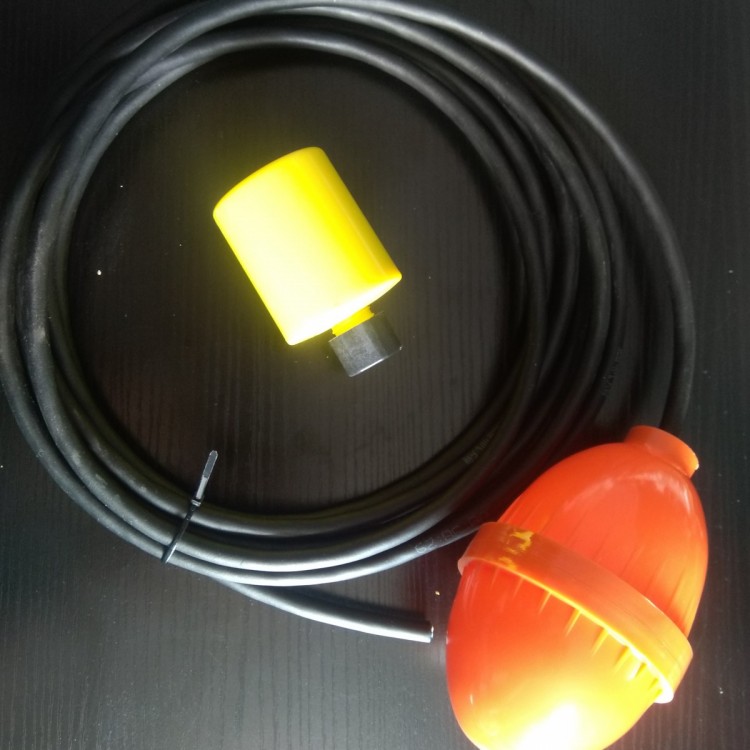
Level switch with a float ball,A spherical magnet is inside the float ball.,Buoy ball hollow,Through a single rod,There is a reed switch within the cylinder.,The float passes through the reed switch position.,Magnet induces reed switch,Reed switch outputs a signal after actuation.
As the water level in the tank rises,Buoyant ball floats up,As the reed switch passes by,Offer a signal,Generally used as a signal to stop water supply.,Or when the water level drops to the upper position,Should be water signal.
Technical Advantages of Buoy Level Switch: The buoy switch does not contain components prone to failure such as bellows, springs, seals, etc. Instead, it uses a straight float to drive the internal magnet of the switch, and the simple lever of the buoy switch enables instant action. The float cantilever angle limit design prevents the float from being vertical. A float ball level switch is a simple, easy-to-use, and reliable level controller. It operates faster and has a longer lifespan than typical mechanical switches; compared to electronic switches, it also boasts strong resistance to load surges.,A single product can achieve multi-point control. It is widely applied in shipbuilding, papermaking, printing, power generation equipment, petrochemicals, food industry, water treatment, electrical engineering, dye industry, and hydraulic machinery. The float switch is a simple, convenient, and reliable level control device with features such as a smaller size, faster speed, and longer service life than general mechanical switches. Compared to electronic switches, it has strong load impact resistance.
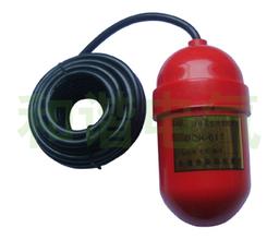
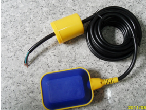
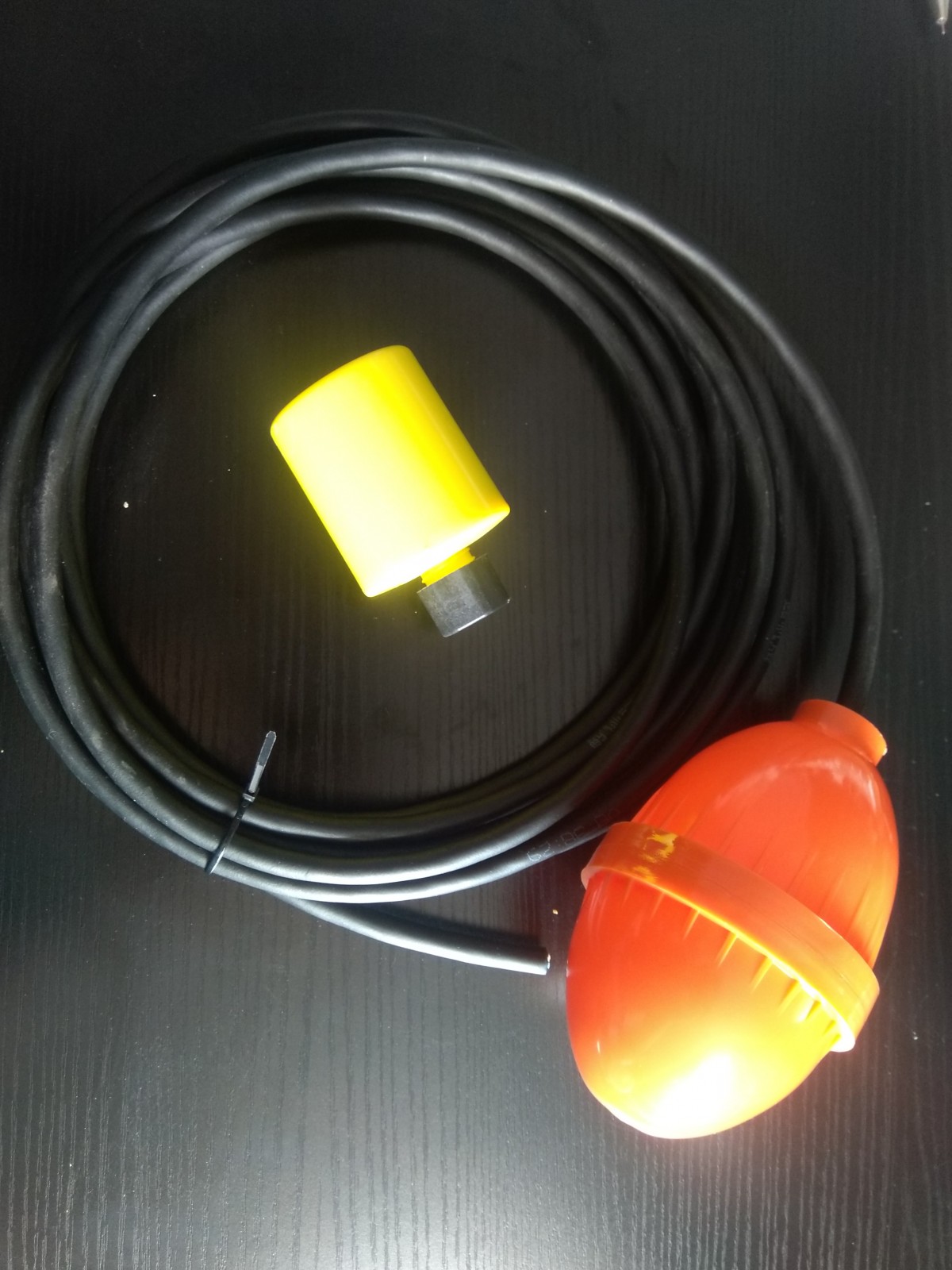
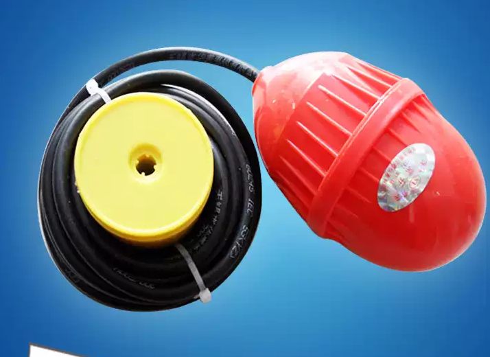
Basic components of the cable float level switch controller consist of a float, cable, rope, and weight, with the reed switch transmitter fully housed within a sealed float. The reed switch is positioned at the base of the float. The magnetic ring and moving hammer are integrated as one unit, which can slide freely on the sleeve. When the ball float's top is facing down, the moving hammer slides to the top of the ball float. The reed switch is away from the magnetic ring, resulting in an open circuit; when the ball's root is facing down, the moving hammer slides to the root of the ball, bringing the reed switch close to the magnetic ring, causing the reed switch to close.

Key Features :
Cutting-edge design and stringent manufacturing processes ensure reliable quality for our products.
The housing is made of engineering plastic, featuring high mechanical strength and good sealing properties.
The cables are made of special materials, offering excellent resistance to oil, acid, alkali, and corrosion.
Simple structure, reliable performance. Stable and dependable output."ON/OFF switch control signals with no accidental operation, high reliability.
Installation is simple, debugging is convenient. By moving and positioning the heavy blocks up and down, you can freely adjust the range of the level control.
Broad application range and diverse installation forms
Multiple Control
Passive Components,Stable and reliable performance, strong anti-interference capability; simple structure, easy installation, low maintenance cost
A variety of materials are available for selection, suitable for use in various occasions.
The float level switch only requires the water level line to be recalibrated before our installation. The switch itself cannot be adjusted. At this point, use a multimeter to test the switch status, and it will open and close near the water line with the water level, indicating no issues. Just ensure the water level line is consistent with the thermal equipment during the installation process. For instance...SORThe level switch, usually marked with water level lines on the cylinder wall, we immerse the switch in a water tray, allowing it to slowly sink, bringing the water level closer to the marked line. As it approaches, you'll hear the microswitch activate.
Note: The working temperature of high-level liquid switches is high, and the water inside is also hot; the density of hot water is less than that of room temperature water. Therefore, the action line of room temperature water is slightly lower than the switch marking line.
Low-level liquid alarm connected to normally closed(NC)High level connects to normally open(NO)This type of switch is still relatively easy to install. The level switch itself usually comes with two or more micro switches, which provide two pairs of normally open and two pairs of normally closed contacts. In application, they are typically..."Receive alarm notification"。
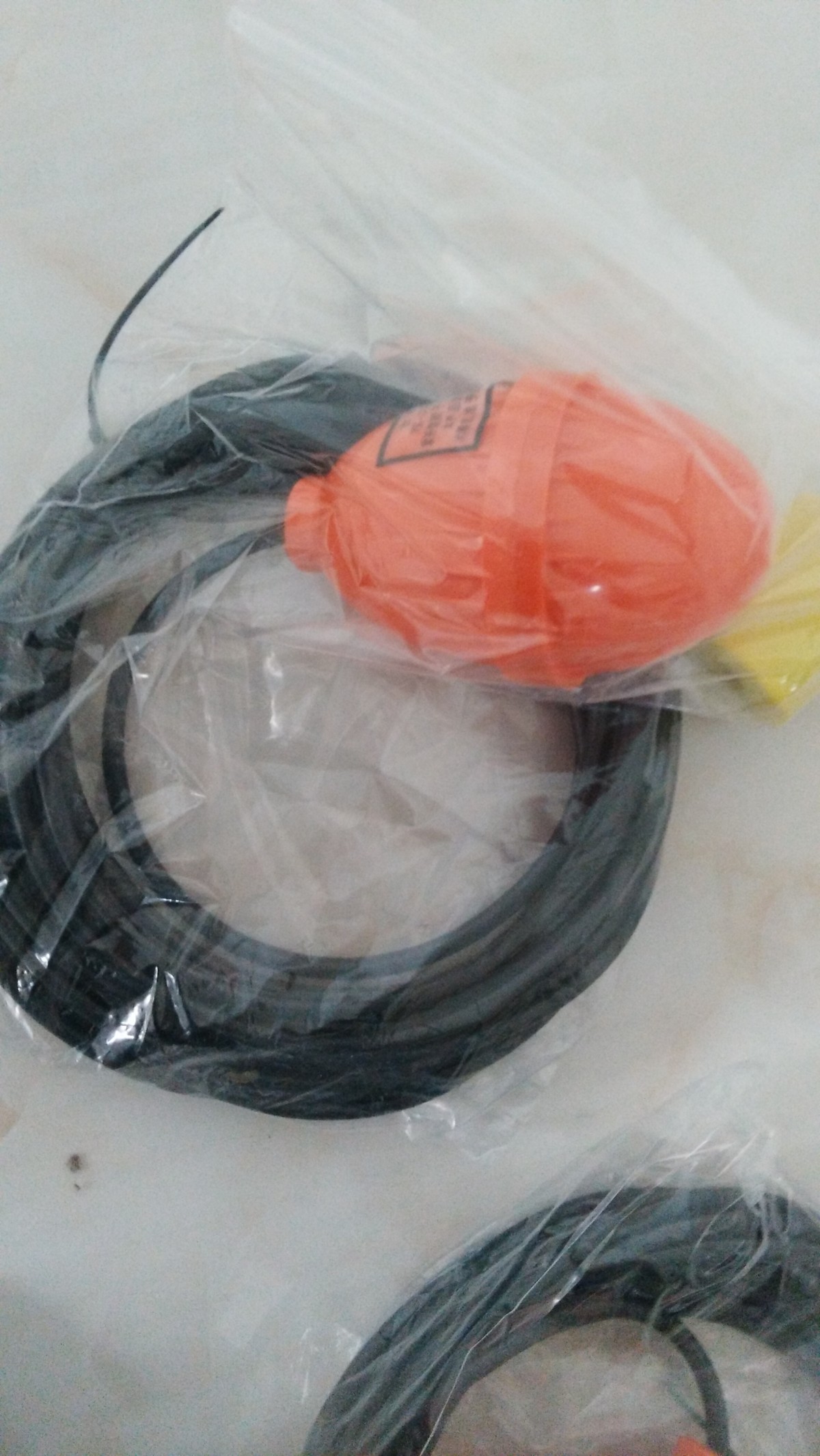
Cable Length:10Rice, or can be extended upon the owner's request.
Float Ball Material: Mercury-Type

Installation Precautions for Water Pump Buoy Switch:
1The installation location should be far from the water inlet; otherwise, the switch may malfunction due to fluctuations at the water inlet.2If the switch device is installed on the container pool wall, additional accessories can be added.LAngle steel bracket.3If the switch device is in the mixing area, a wave guard pipe or a wave guard baffle can be installed.4Select a flanged pipe with an inner diameter larger than the ball diameter.5It is recommended to use multi-core cables during wiring.6The controlled circuit load must match the capacity of the float switch contacts.7The specific gravity of the liquid being tested must be greater than that of the float.8The action point of the float ball has been adjusted according to the customer's order at the time of manufacture. Please do not adjust the position of the float ball arbitrarily. When the float ball switch is used in circuits with electrical inductive loads such as motors, relays, solenoid coils, etc., it is recommended to parallel a protective circuit at both ends of the load, such as:RCBuffers, variable resistors, diodes, etc. Note: Do not directly connect the float switch to the solenoid valve, motor, or solenoid switch. When using a float switch with capacitive loads such as capacitors, incandescent bulbs, or long cables, a surge current will be generated between the switch contacts; it is recommended to parallel a protective circuit at both ends of the float switch, such as a current-limiting resistor or a surge absorber.