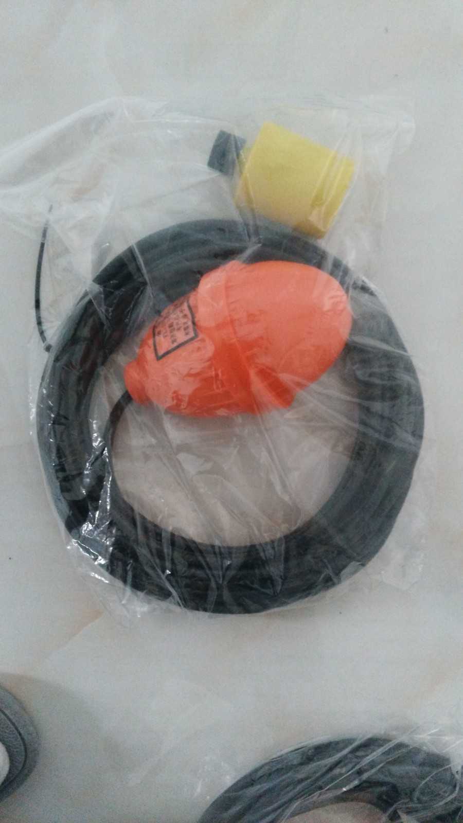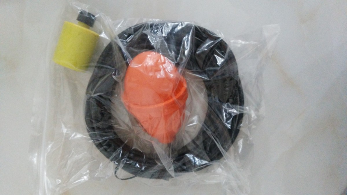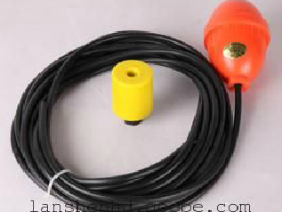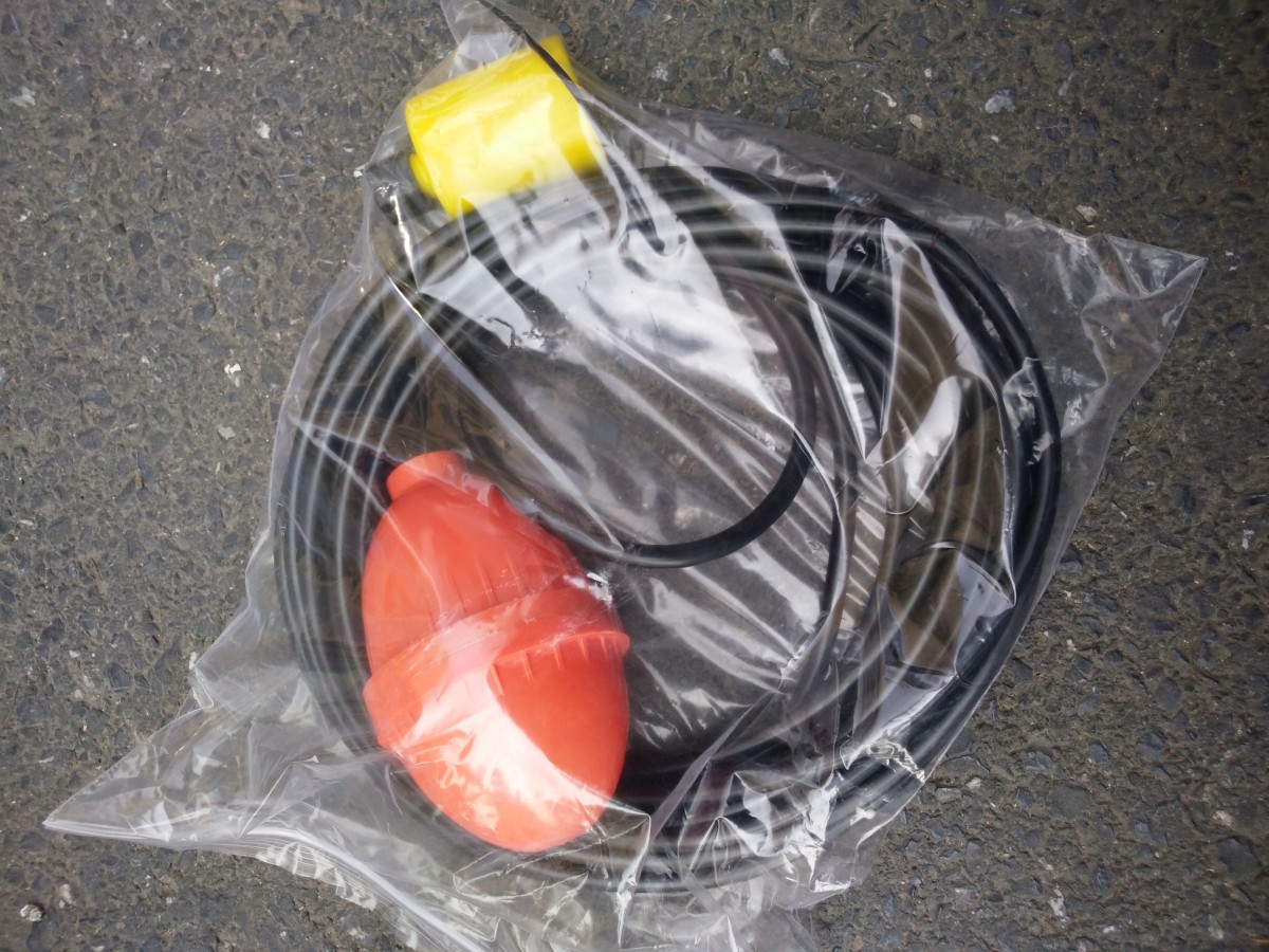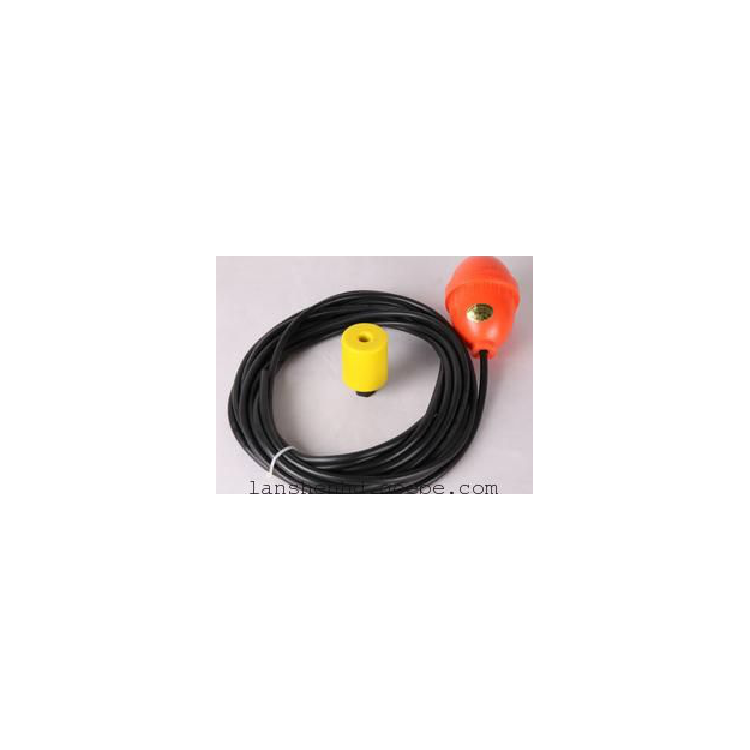


Float level gauge, also known as a float switch, submersible pump float, float switch, water pump float switch, float micro-motion switch
Model:FK2
FK2Cable float level switch, featuring high sealing performance floating switch..CategorizedFK2 WithFK3 ,FK2Is a secondary continuous output,FK3It is a three-line normally open and normally closed switching output..The cable float level switch is suitable for controlling the operation of liquid pumps.,Level Adjuster,It can also be installed on submersible pumps to control and protect the motor..High-seal performance is ensured through the use of polypropylene injection..
Buoy Switch Technical Parameters
Rated Current/Voltage:10A/220VAC SPDT.Operating Temperature:-10Celsius ~80(Plastic) Celsius.Control Accuracy:±0.05m.Applicable Medium:Clear water, wastewater, oils, and acidic or alkaline liquids with concentrations below medium.. Length:5m、10m、15mCustomizable upon request.Electrical lifespan:100000Next.
FK-2Type Floating Ball Open Closed
Built-in switch mechanism, no blocking or jamming issues.
On-site fixed installation, liquid level can be freely set.
Excellent corrosion resistance and long service life.

Application and Features:
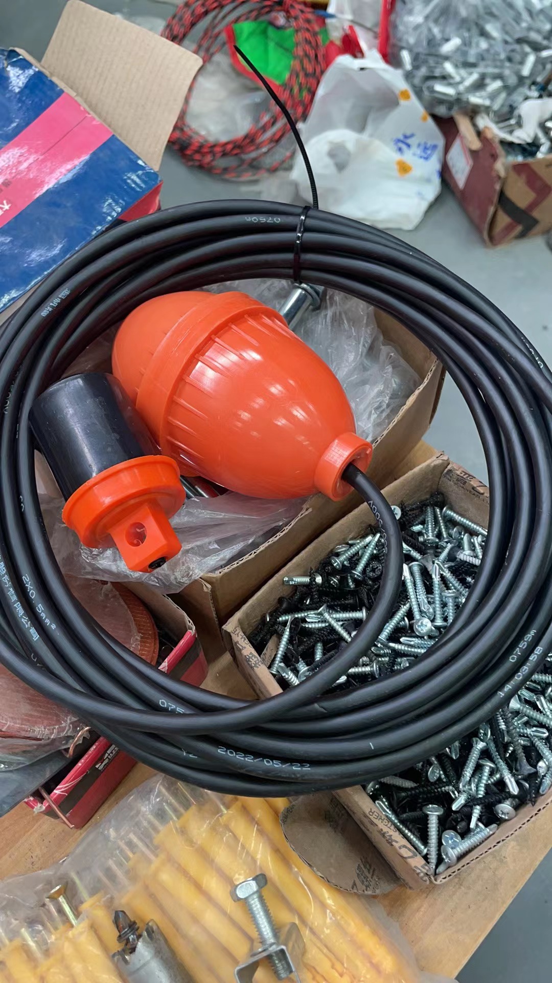
FK2The float switch's housing is made of engineering plastic, featuring a fully enclosed mercury switch installed within its sealed ball. It operates by utilizing the buoyant force of the liquid, with the ball flipping as the liquid level rises or falls, thereby toggling the internal switch to connect or disconnect. Its operation is reliable and has a long service life, effectively controlling the pump's start/stop and alarm functions. This product is widely used in automatic water supply and drainage control systems.
Technical Data & Specifications:
Model:FK-2Drainage Type Built-in Normally Open Switch
Higher Operating Voltage:AC220V DC110V
Higher Working Current:1A(COSФ≥0.4)
Cable Length:10Rice
Outside Diameter of Sphere:74mm
Sphere Length:132mm
Sphere Weight:150g
III. Terms of Use:
Medium Specific Gravity: 0.5~2.0g/CM3
MediumPHValue:6-8.5
Higher Working Temperature:-10℃-+60℃
High working pressure:0.15Mpa
Section 4: Basic Working Principle
FK2Buoy switch utilizes the buoyant force of the liquid to automatically flip the buoy as it rises or falls, emitting control signals; position2Location1It is the flip point when rising, at which time the internal mercury switch of the float ball changes from open circuit to closed circuit. Position2Location3It's the turning point of the decline; at this point, the internal mercury switch of the float ball changes from closed to open circuit.
V. Installation Method and Usage Instructions:
1.The float ball's action length should be less than the distance between the fixed support and the wall.
2The float ball height at lower water level must be higher than the submerged water level of the pump.
3The float switch should be installed at an appropriate distance from the pump's suction inlet to prevent it from being drawn into the water intake.
4The float switch should be installed at an appropriate distance from the water flow entrance to prevent incorrect sensing due to wave impacts. If necessary, please add a wave shield.
5The float cable is directly connected to the control box. Avoid intermediate joints. Never immerse the cable joint in water.

Special Reminder: All resistance value tests mustMultimeter requiredDo not use a megohmmeter for measurement!
Otherwise, it could damage the float switch!
The magnetic float of the float level switch moves up or down with the liquid level, causing the reed switch chip at the set position within the sensor tube to activate, emitting a contact open (close) switching signal.
One or more reed switches are installed inside a sealed non-magnetic tube, which is then passed through one or more hollow spheres containing circular magnets. As the liquid rises or falls, it moves the spheres up or down, causing the reed switches within the non-magnetic tube to either close or open, thereby outputting a switch signal.
FK2Ball float switchA simple structure, easy to use, and safe and reliableLevel control deviceIt features a smaller size, faster speed, and longer operational lifespan compared to conventional mechanical switches. Additionally, it boasts strong resistance to load surges, making it ideal for applications in shipbuilding, papermaking, printing, generator equipment, petrochemicals, food industry, water treatment, electrical engineering, dye industry, and hydraulic machinery, among others.
How to wire a three-phase submersible pump using a float switch
1First, measure the resistance of the three lines of the float ball-controlled three-phase pump pairwise, and remember them.Please provide the Chinese content you would like translated into American English.The two high-value lines and their resistances, the third line is the connection point for the main and auxiliary lines.
2Measure the resistance between the contact and both ends (the sum of these two resistances must equal the aforementioned)Please provide the Chinese content you would like translated into American English.The lower value is the main winding, while the higher value is the auxiliary winding.
The terminal junction of the winding connected in series with the capacitor is the secondary winding. Assuming the secondary winding resistance isR1The main winding resistance isR2No content provided for translation.R1>R2.(Main winding has high power and low resistance) Use a multimeterMeasure and compare the resistance values between each pair of terminals.
First, locate the terminal of the auxiliary winding connected via a capacitor: there is resistance between it and the other two terminals.Please provide the Chinese content to be translated.High ValueR1SeriesR2),
With the two major valuesR1Find the two remaining terminals with the lower resistance.R2And 2nd small resistanceR1The terminal that connects to the neutral wire, which is the common terminal for both the primary and secondary windings. This completes the connection of the float ball control circuit for the three-phase pump.
Float switch with three wiresDefinition and Wiring Method:
Three wires, one being a common terminal. If starting the pump at high water level, position the float ball upwards and connect the two wires that are shorted together. If starting the pump at low water level, position the float ball downwards and connect the two wires that are shorted together.
Float ball level controller, which uses a magnetic float ball to generate multi-point switch signals. Dry reed switches are installed at different heights inside the conduit. As the magnetic float ball rises and falls with the liquid level, the magnetic steel inside the float ball causes the corresponding reed switch at the respective position to close or open, emitting switch signals, and it has a self-holding function, so it is not afraid of power outages. After power is restored, the working state of the contacts can still accurately reflect the true liquid level of the tested medium. The switch signals are dividedATypes (normally open, normally closed) andBTwo types (normally closed, instant break) available, user selects as needed.