


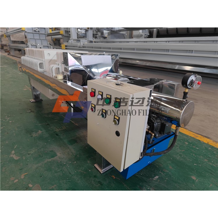


Sand and Water Separator LSSF-260, LSSF-320
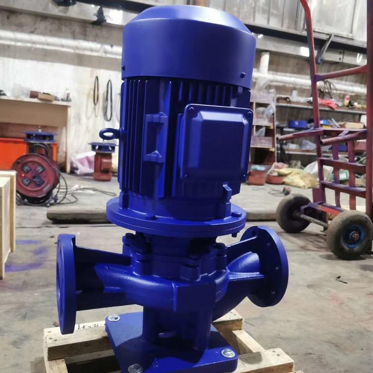
380V voltage
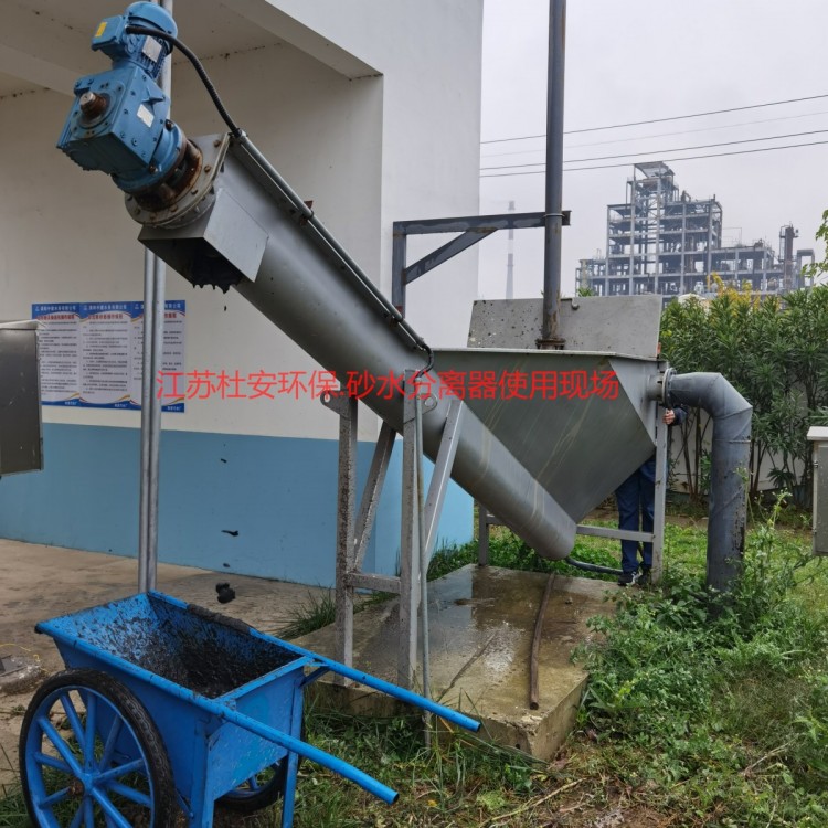
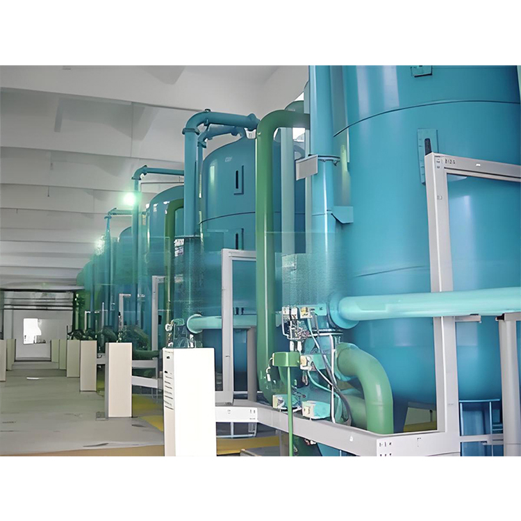
I. Sand and Water Separator Overview:
Sand separator is an auxiliary equipment for the sand removal system in sedimentation tanks, consisting of a sedimentation basin, shaftless spiral shaft,U-shaped helical grooves, water tanks, and baffles are assembled to separate sand from sand-water hydrates discharged from the sedimentation pond, facilitating transportation.
Section 2: Working Principle of the Sand and Water Separator
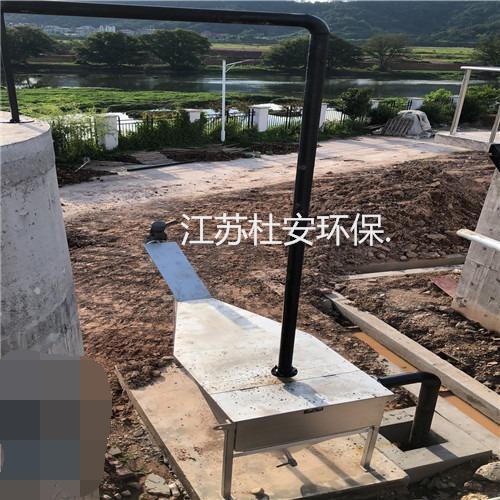
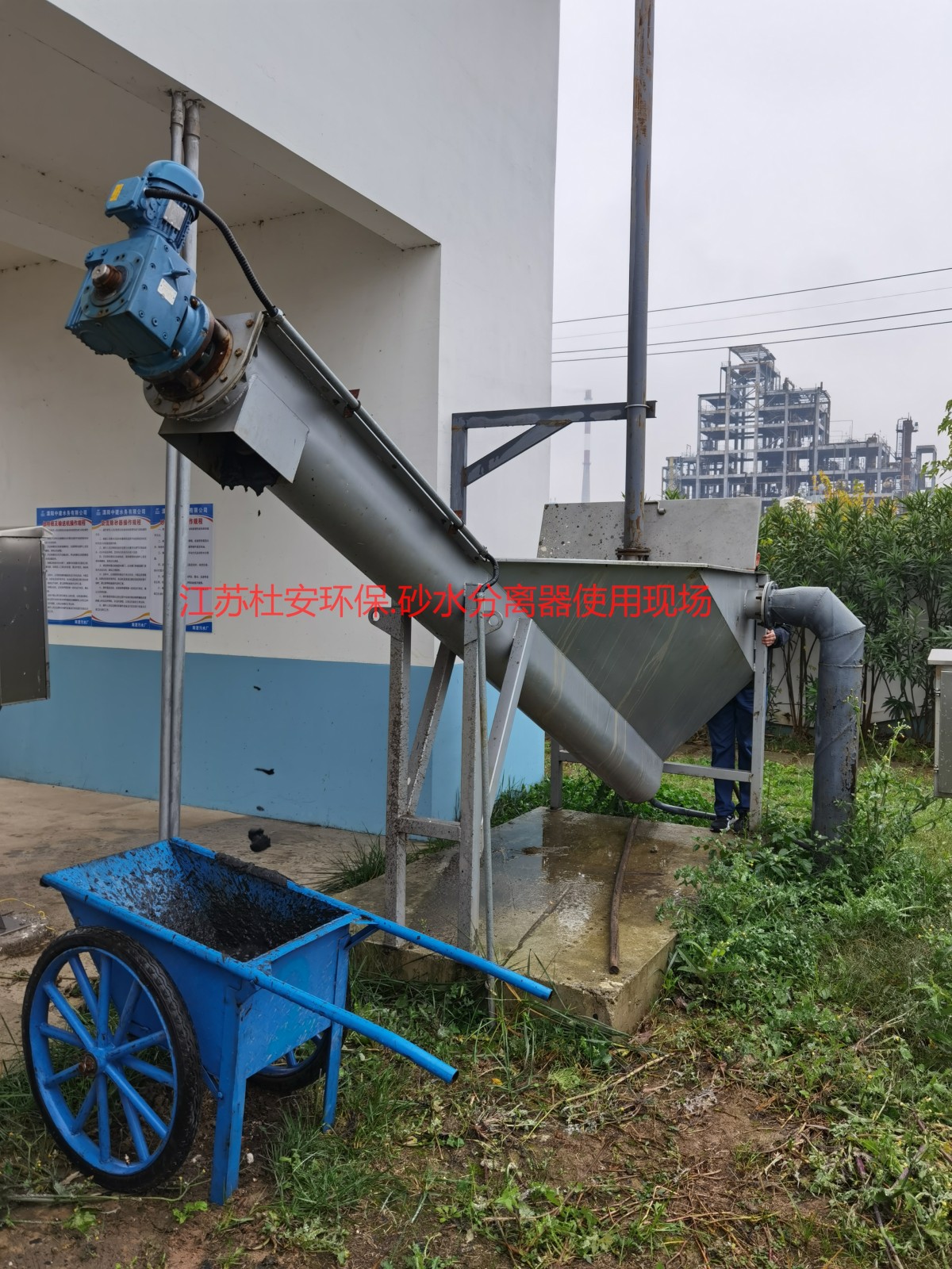
Sandy hydrates are introduced into the water tank from the top of the separator, where the sand and gravel settle at the bottom of the trough. Under the conveyance of the shaftless spiral, the sand and gravel are transported out.Bottom lifting of U-channel, continuously pushing until the sand and gravel are fully dehydrated, then discharged into the sand bucket. The separated water is transported to the intake pool.
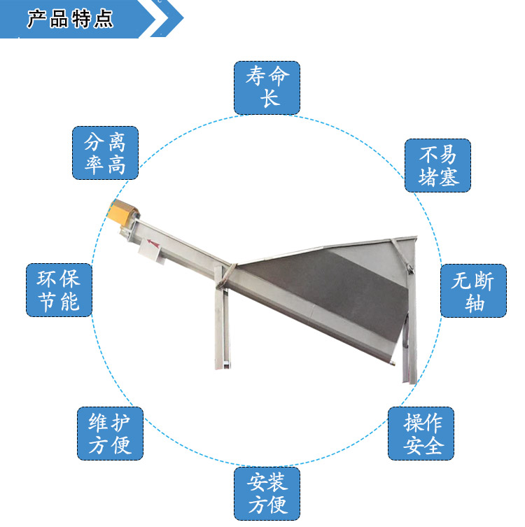
III. Features of the Sand and Water Separator:
The sand-water separator features an integrated structure, which is compact, lightweight, and highly efficient in operation.
2. The sand-water separator can separate particles with a size of >=0.2mm, with a recovery rate not less than 98%.
3. The U-trough of the sand-water separator features an axisless helix, which boasts sufficient strength to prevent deformation during operation and is easy to maintain.
4. All components of the sand-water separator's sand-water separation pond are made of stainless steel.
5. The U-shaped channel of the sand-water separator features ample replaceable linings, a simple structure, and a long service life.
6. The shaft of the shaftless spiral in the U-shaped channel of the sand-water separator is waterproof, dustproof, and wear-resistant.
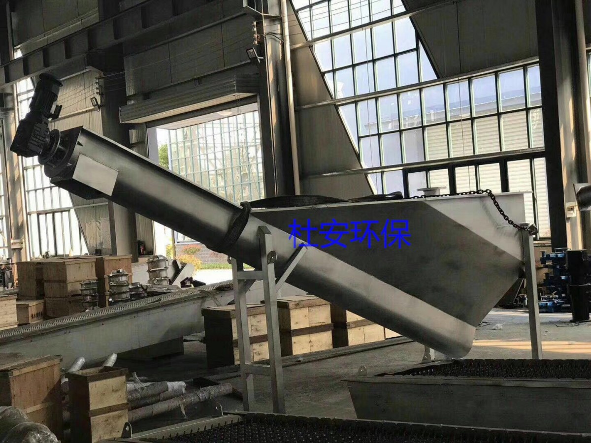
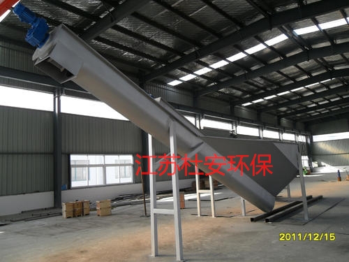
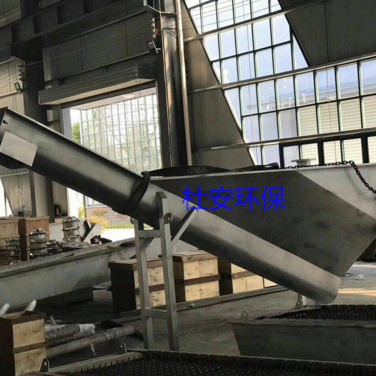
Section 4: Structural Diagram of Sand and Water Separator
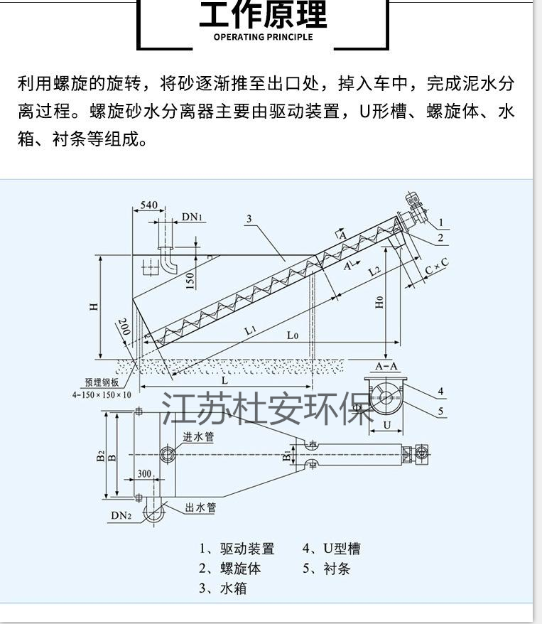

Duwan LSSF-260 & LSSF-320 Sand and Water SeparatorPrimarily composed of shaftless spiral, strips.U-shaped channels, water tanks, guide vanes, discharge weir drives, and the like are composed.
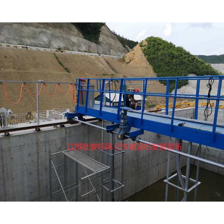
Installation and tuning
1. If not specified in the order contract, the machine is factory-equipped with a ground stand, adjusted to the user's installation angle or discharge height, and secured with expansion bolts during installation.
2. The installation angle error of the equipment is ±1 degree.
3. Equipment must not collide or slip during lifting, and effective measures must be taken to protect the stainless steel surface from scratches, wear, and dents.
4. Check the reducer oil level before starting up. Change the lubricating oil after * uses or every 300 hours. For equipment running continuously for over 16 hours, replace the oil every 2500 hours. For equipment running 8 hours a day, the interval can be extended to 4000 hours.
5. During the power-on test, it should be manually activated first to ensure there is no part friction before entering normal operation.
Usage and Maintenance
Operators must be trained and qualified before they can start operating.
2. Equipment is maintained in accordance with regular inspection, maintenance, repair, and lubrication management procedures.
3. Conduct daily inspections of machine operation, ensuring no abnormal noises, checking for leaks in seals, and adding the appropriate amount of bearing grease. Monthly, check the oil level in the drive unit gear box and adjust it to the required height.
Every two years: dismantle and overhaul the equipment, disassemble and clean the reducer, replace worn parts, replace seals and worn bushes, inspect and align the helix, etc.
5. Shutdown due to malfunction should be investigated for the cause, and the issue resolved before restarting the machine.
6. When machinery is shut down for three days or more, flush or remove internal materials to prevent them from drying and caking.
7. During winter when temperatures are low, frost protection should be ensured. Blockages and ice formation should be cleared before operation. If supplied as a complete set with other equipment, the control buttons are centralized in a control box.
Operation of the sand water separator:
The sand-water separator should be placed horizontally on the operation table, and the bottom must be securely bolted to the ground. No significant vibration should be detected before operation.
The sand-water separator requires mechanical oil to be added to the reducer before use.
After powering on the sand-water separator, observe whether the screw rotates in the correct direction and whether it consistently rotates towards the logistics outlet.
After the sand-water separator is turned on, inspect the material for any hard debris. If there is any abnormality with the conveyor, stop and inspect immediately.
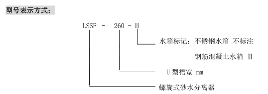
Spiral Sand and Water Separator Ordering Requirements:
1Please write the full name according to the model notation.
2Application Environment (indoor, outdoor, and others)
3If reinforced concrete water tanks are used, engineering design documents for the relevant sections should be provided.