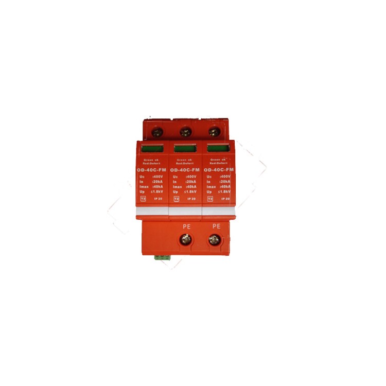
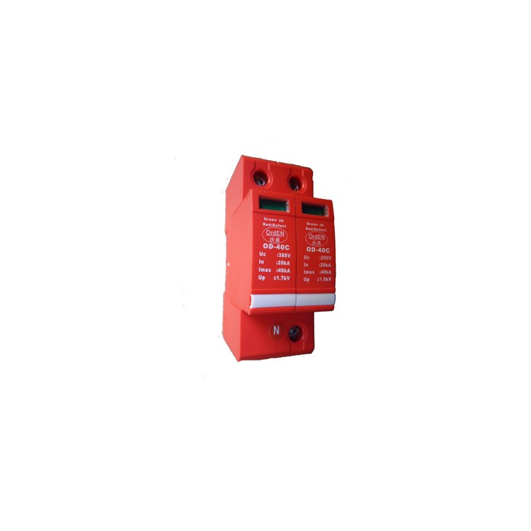


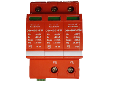
I. Product Introduction:
OrdENThe surge protection module is designed, manufactured, and tested in accordance with international standards IEC61643, national standards GB18802.1, and industry standards QX10.1-2002 for meteorology and YD/T1235.1-2002 for communication. The product is strictly controlled under the ISO9001 quality assurance system.
This product is widely used in mobile communication base stations, microwave communication offices/stations, telecommunication equipment rooms, industrial mines, and civil aviation power systems, including various power stations, switchrooms, distribution panels, AC/DC switchboards, switch boxes, and other critical equipment susceptible to lightning strikes.
◆ Utilizes a pressure-sensitive resistor chip for stable and reliable performance.
◆ Features a plug-and-play design for easy replacement;
Mechanical thermal release device with high sensitivity.
Modular sealing design, high flow rate, and lower protection level.
◆ Single-phase, capable of being combined into multi-pole for various grid configurations.
◆ Equipped with a degradation display window, and can be optionally fitted with a remote遥信output interface.
The shell is made of high flame-retardant materials, offering high safety performance.
35mm track mounting, standard modular design.
◆ The product is available with an optional FM alarm feature.
◆ Our products offer a wide range of colors and styles, catering to all aesthetic preferences!
Product parameters are for single module. For three-phase, please change the model to /4. For single-phase, please change the model to /2.
ThreeTechnical Specifications:
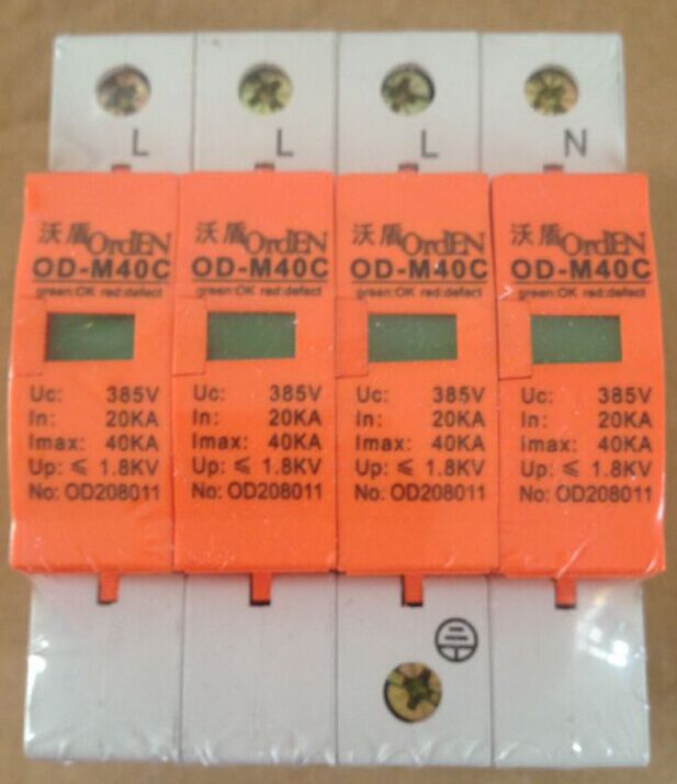
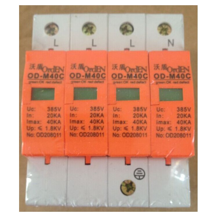
Product Model (Single Module Parameters)
| OD-M40C/4 OD-M40C/4-FM
|
IEC Category/VDE Specification Grade/EN Type
| II/C/T2
|
Working Voltage Un (V)
| 220V
|
Continuous Operating Voltage Uc (V)
| 320V
|
Rated Discharge Current In (kA) 8/20μs
| 20KA
|
Discharge Current Imax (KA) 8/20μs
| 40KA
|
Voltage Protection Level Up (KV)
| ≤1.5
|
Response Time (ns)
| <100
|
Backup yarn (optional)
| 63A
|
Degradation Indicator
| Degradation Indicator Window
|
Work Environment
| -40℃ to +85℃, relative humidity < 95%
|
Product Dimensions
| 18mm
|
Conductor cross-sectional area for installation
| 2.5mm2-50mm2 soft wire/multi-strand copper-core wire
|
Protection rating, conforms to IEC 60529/EN 60529
| IP20
|
Insulating Shell Material
| Flame-retardant PBT
|
|
IV. Product Installation Instructions:
1. Power must be disconnected before installation, and operation with live electricity is strictly prohibited.
2. Suggest connecting a fuse or an air circuit breaker in series at the front end of the lightning protection module.
3. SPD is parallel installed at the power input end of the building's distribution box or in the server room. The product is for track-mounted installation, and the Kevin connection type can be adopted if conditions permit.
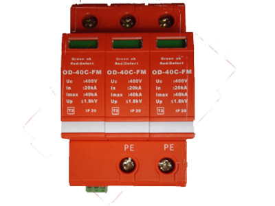
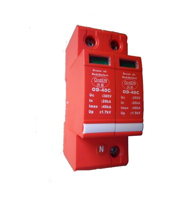
4. Please connect according to the installation diagram provided, where L stands for phase wire, N for neutral wire, and PE for ground wire. Do not connect them incorrectly. After installation, close the circuit breaker switch and check if the operating status is normal.
5. During use, the lightning protection module should be regularly inspected and the status of the fault display window checked. When the fault display window shows red or the remote signal terminal outputs an alarm signal, it indicates a fault in the lightning protection module, and it should be repaired or replaced promptly.
6. Suitable for indoor operation; if installed outdoors, a waterproof housing must be added.
All connections must be firm and reliable electrical connections.
8. Lightning protection grounding should comply with the lightning protection regulations, with grounding wires being as thick and short as possible, and the grounding resistance should be less than 10Ω.
I. Product Introduction:
OrdENThe surge protection module is designed, manufactured, and tested in accordance with international standards IEC61643, national standards GB18802.1, as well as meteorological industry standard QX10.1-2002 and communication industry standard YD/T1235.1-2002. The product is strictly controlled under the ISO9001 quality assurance system.
This product is widely used in power systems for mobile communication base stations, microwave communication offices/stations, telecommunication rooms, industrial factories and mines, civil aviation, etc., such as various power distribution stations, distribution rooms, switchboards, AC/DC distribution panels, switch boxes, and other critical equipment prone to lightning strikes.
◆ Utilizes a pressure-sensitive resistor chip for stable and reliable performance.
◆ Features a plug-and-play structure for easy replacement;
Mechanical thermal release mechanism with high sensitivity.
◆ Modular sealing design, high flow rate, lower protection level;
Single-phase, can be combined into multi-pole for use in different grid configurations.
Features a degradation display window, and can be equipped with a remote遥信output interface.
The shell is made of high flame-retardant materials, offering high safety performance.
35mm track mounting, standard modular design.
The product can be optionally equipped with FM alarm function.
◆ A wide variety of product colors and styles to meet all aesthetic requirements!
◆ Product parameters are for single module only. For three-phase, please change the model to /4. For single-phase, please change the model to /2.
ThreeTechnical Specifications:
Product Model (Single Module Parameters)
| OD-M40C/4 OD-M40C/4-FM
|
IEC Category/VDE Specification Grade/EN Type
| II/C/T2
|
Working Voltage Un (V)
| 220V
|
Continuous Operating Voltage Uc (V)
| 320V
|
Named Discharge Current In (KA) 8/20μs
| 20KA
|
Discharge Current Imax (KA) 8/20μs
| 40KA
|
Voltage Protection Level Up (KV)
| ≤1.5
|
Response Time (ns)
| <100
|
Backup yarn (optional)
| 63A
|
Degradation Indicator
| Degradation Indicator Window
|
Work Environment
| -40℃ to +85℃, relative humidity < 95%
|
Product Dimensions
| 18mm
|
Conductor cross-sectional area installation
| 2.5mm2-50mm2 soft wire/multi-strand copper core wire
|
Ingress Protection (IP) rating, conforms to IEC 60529/EN 60529
| IP20
|
Insulating Shell Material
| Flame-retardant PBT
|
|
Section 4: Product Installation Instructions
1. Power must be disconnected before installation, and live operations are strictly prohibited.
2. Recommend connecting a fuse or an air switch in series at the front of the lightning protection module.
3. SPD parallel installation at the power input end of building distribution boxes or server rooms, with a track-mounted design. The Kelvin connection method can be adopted if conditions permit.
4. Please connect according to the installation diagram provided, where L is the phase wire, N is the neutral wire, and PE is the ground wire. Do not connect incorrectly. After installation, turn on the automatic circuit breaker switch and check if the operating status is normal.
5. During operation, the lightning protection module should be regularly inspected and the status of the fault display window checked. If the fault display window shows red or the remote signal terminal outputs an alarm signal, it indicates a fault in the lightning protection module, and prompt repair or replacement should be carried out.
6. Suitable for indoor operation; if installed outdoors, a waterproof housing must be added.
All connections must be secure and reliable electrical connections.
8. Lightning protection grounding should comply with lightning protection specifications, with grounding wires as thick and short as possible, and the grounding resistance should be less than 10Ω.