


(1) Construction Process:
Assemblies of embedded base components → Sectional jointing of poles → Insertion of wire ropes and cables → Installation of head → Hoisting → Adjusting the verticality of the pole → Power connection → Installation and adjustment of light panel → Installation of lighting fixtures → Adjustment
(II) Construction Method:
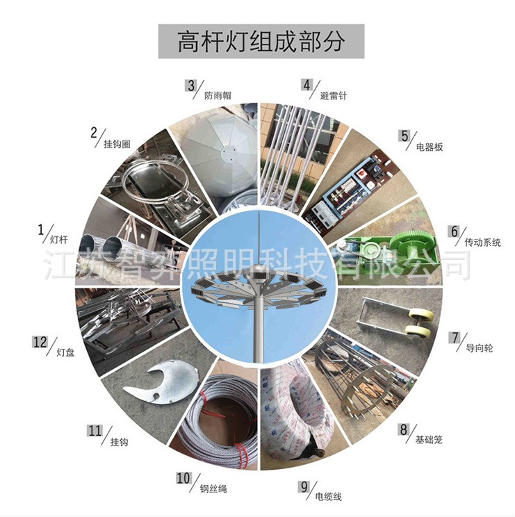
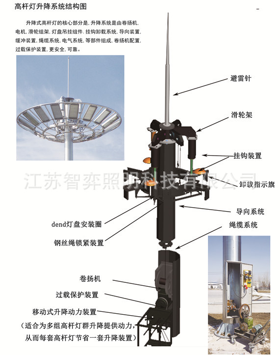
The winch and electrical panel for the telescopic flagpole are pre-installed within the pole prior to shipment, with the hook assembly and head already assembled into a complete unit. The entire system is assembled and debugged in our factory. The goods delivered to the site are divided into pole sections, head assembly, hook assembly, rain cover, light panel, and accessories (such as wire rope, cables, lightning rods, light panel brackets, electric tools, etc.).
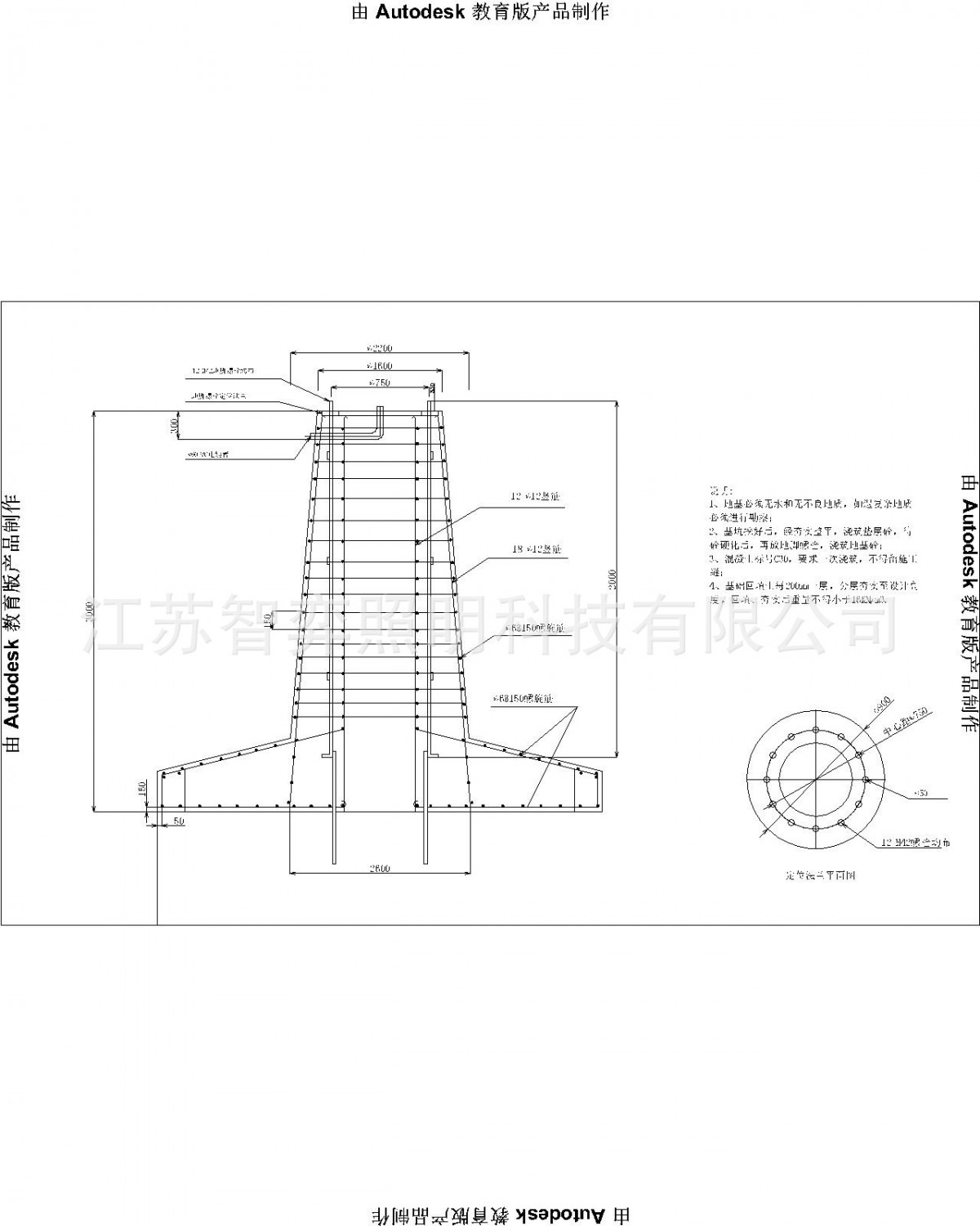
1. Organization of foundation embedment parts:
Clean debris from the concrete foundation surface, remove protective covers from the bolts of embedded components, check the spacing dimensions between bolts (including diagonal dimensions), and confirm that the bolt positions match the dimensions shown in the drawings. Inspect the bolt threads for damage; if necessary, repair the threads to ensure the nuts can be freely tightened.
2. Socketing of the rod body:
Prior to the commencement of the sleeve assembly, a fine steel wire or wire, longer than the rod height, should be threaded through the electrical door into the rod body. This will serve as a guide for threading the wire rope and cables later on. The process of threading the wire or wire should be carried out simultaneously with the sleeve assembly. (See Figure 1)
Start from the very bottom section of the sleeve and proceed upwards, section by section.
Position the base section with the flange near the foundation in the appropriate location (place the electrical maintenance door upwards), ensuring the flange is on the ground. Use wooden wedges to elevate the front end of the base section approximately 1.5 meters from the front, allowing the front end of the base section to clear the ground, leaving sufficient space for inserting the upper section rod.
Socket depths on the base section, varying socket depths between each rod section due to different rod diameters, can be found on the drawing.
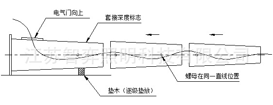
Nuts are welded on both sides of the rod body for hanging and tightening the wire rope. When lifting, confirm the position to ensure that the nuts of the upper and lower sections are aligned in a straight line.
Lift the rod body from the previous section with a crane, aligning the larger end with the front end of the base section, and slowly insert it, aiming for maximum depth. Similarly, place wooden wedges at the front end of this section.
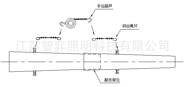
Tighten bolts on the nuts on both sides of the upper and lower rod bodies, and securely attach the tensioned wire rope and hand winch as shown in the following illustration on both sides of the rod bodies.
Simultaneously tighten the manual winch on both sides of the rod until the sleeve depth mark is reached. If resistance is felt during the tightening, use a hammer to strike the sleeve section of the rod to create vibration, assisting in the rod's tight fit. Use a wooden board or other padding when striking to prevent surface damage to the rod. (See Figure 2)
Following the aforementioned steps and methods, sequentially connect the other sections of the rod.
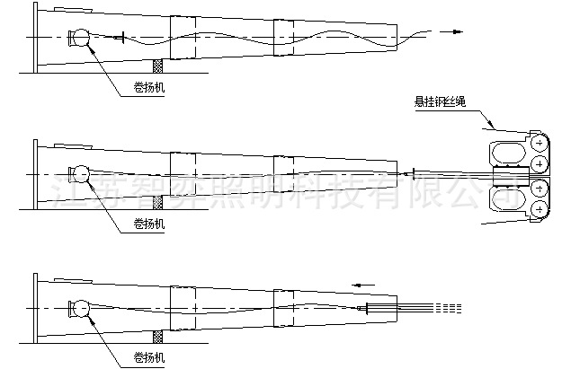
3. Wire Rope and Cable Lacing
After the rod sleeve is assembled, connect the rigging connector to the winch's main steel wire rope, then connect and secure it to the guide wire left in the rod from within the electrical door. Release the winch to allow the main steel wire rope to unwind from the drum (refer to the external electric winch lifting pole operation manual if using electric operation). Simultaneously, pull the guide wire at the other end of the rod to pull the rigging connector out of the rod's small end. Move the head to the appropriate position at the front end of the rod, and thread the ends of the three suspended steel wire ropes without loops and the cable through the head sleeve, through the pulley groove, and out through the head opening. Then connect the other end of the suspended steel wire rope with loops to the rigging connector (the connection method of the cable is shown in the figure). Operate the winch to retract the main steel wire rope, causing the rigging connector to retract and enter the rod (about 100cm into the rod). (See Figure Three)
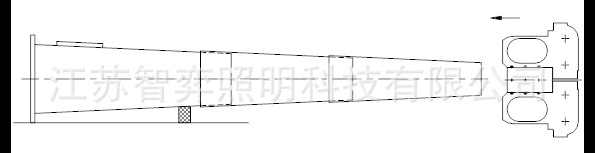
4. Head Mounting:
Lift the front end of the rod, which has been fitted with sockets and threaded cables, using an object (with the electrical door of the rod facing upwards), ensuring the height is sufficient to allow the installed head to clear the ground.
Tighten the set screw onto the nut of the head sleeve, lift the head with a crane, and insert it into the rod body. The fork position with the cable pulley on the head should align with the electrical door's orientation. (See Figure 4)
Tighten the set bolts in sequence, adjust the bolt insertion depth, ensuring the clearance between the head sleeve and the rod body is consistent (i.e., align the axis of the head sleeve with the axis of the rod body). The purpose is to have the three pulley shafts at the same horizontal plane after the rod is erected.
Pull three suspended steel wire ropes and cables towards the bottom of the pole to the level above the electrical door, ensuring the distance from the ground can be connected to the fixed point of the light plate. Temporarily tie them to the pole with ropes to minimize interference during the hoisting process.
Later, install a rain cover, lightning rod, and connect the jumper wires at the top.
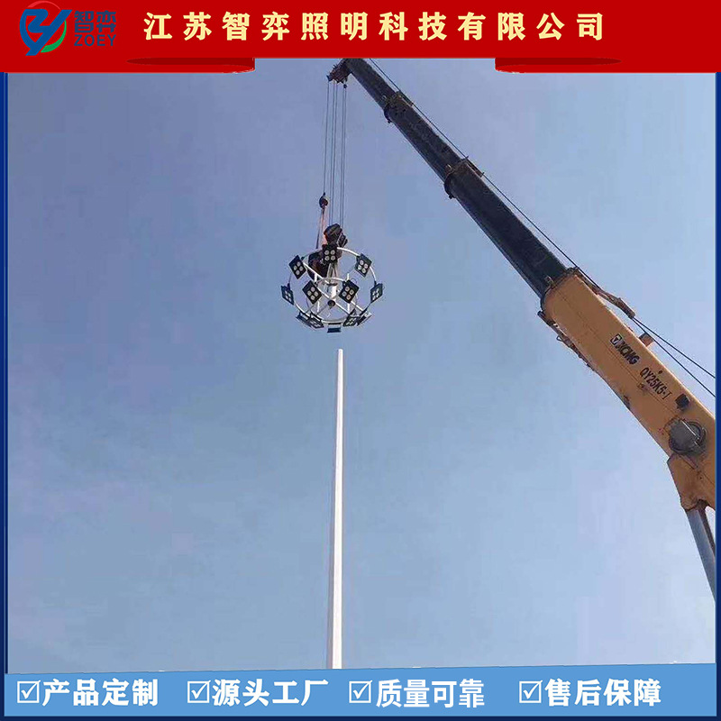
5. Hoisting
After completing the above steps, please carefully inspect and verify to ensure there are no omissions and everything is secure, then you can prepare for lifting operations.
Based on the specific conditions of the 35-meter, 15-meter, and 8-meter steel lamp posts, select cranes and hoisting equipment. During the lifting process, the site supervisor will统一指挥 to ensure the entire lamp post installation proceeds reliably and orderly on the road.
Theodolites and level gauges are used to check verticality, with allowable deviation: 2H/1000 for lifting and lowering, and 3H/1000 for the 10-meter light pole, not exceeding 20 (H is the height of the light pole, in mm).
Please note the following points for the hoisting of telescopic high poles:
5.1 The head of the machine should be positioned below the light pole during the lifting and installation process.
5.2 The lifting point should be at two-thirds of the rod's length.
5.3 The lifting equipment load must meet the weight of the rod body.
5.4 The lifting point should be positioned to facilitate the placement of the light pole in the pre-determined orientation.
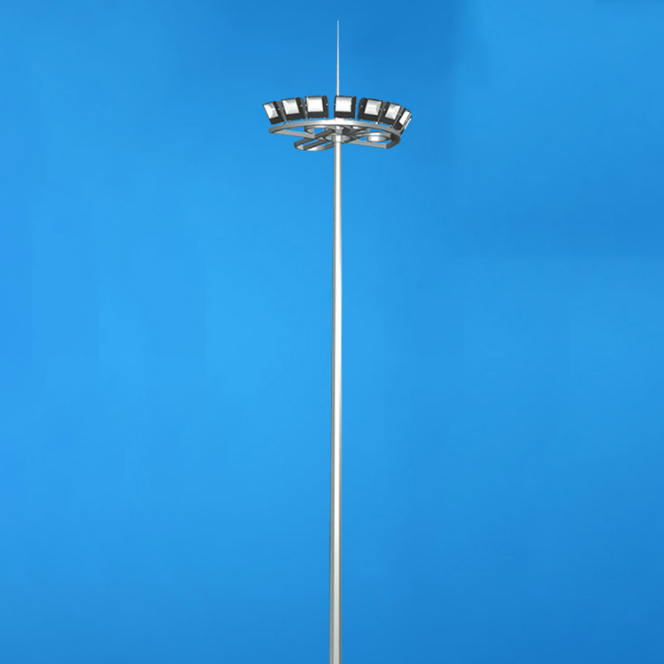
6. Lighting panel installation and adjustment:
Tighten the set screws onto the lamp base sleeve nut, lift the lamp base with a crane, and fit it over the front end of the pole. Gradually tighten the set screws, adjusting the screw depth to maintain consistent clearance between the lamp base sleeve and the pole body (aligning the lamp base sleeve axis with the pole axis).
Later, install lightning rods on the light panel.
7. Cable Passing
Prior to stringing the cables, a guiding steel or iron wire should be inserted first. This step can be pre-completed during the jointing of the poles (refer to the section on pole jointing) or after the base is mounted on the pole.
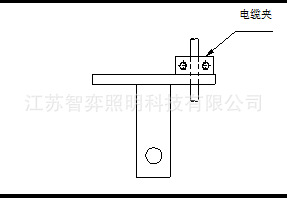
At the front end of the pole or the cable entry hole of the lamp disc, wrap and secure the guide wire around the cable. Pull the guide wire while coordinating the insertion of the cable, threading it into the pole body.
8. Lighting Installation:
Install lighting fixtures at the designated positions on the light panel, connect the wiring, apply power, and conduct a 24-hour lighting test.