


I. Design Basis:
Meets the requirements of the "Automotive Industry Standard of the People's Republic of China" (QC/T523—1999) "Test Methods for Automotive Propeller Shafts on Test Beds" and JB/T 10189-2010 "Rolling Bearings - Constant Velocity Universal Joints for Automotive Use and Their Assemblies" for static torsional test of automotive propeller shafts. Conducts torsional strength and static torsional stiffness tests on automotive propeller shafts.
II. Test Bench Structure and Working Principle:
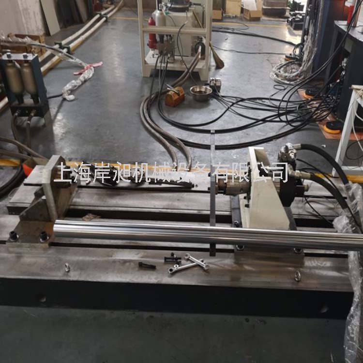
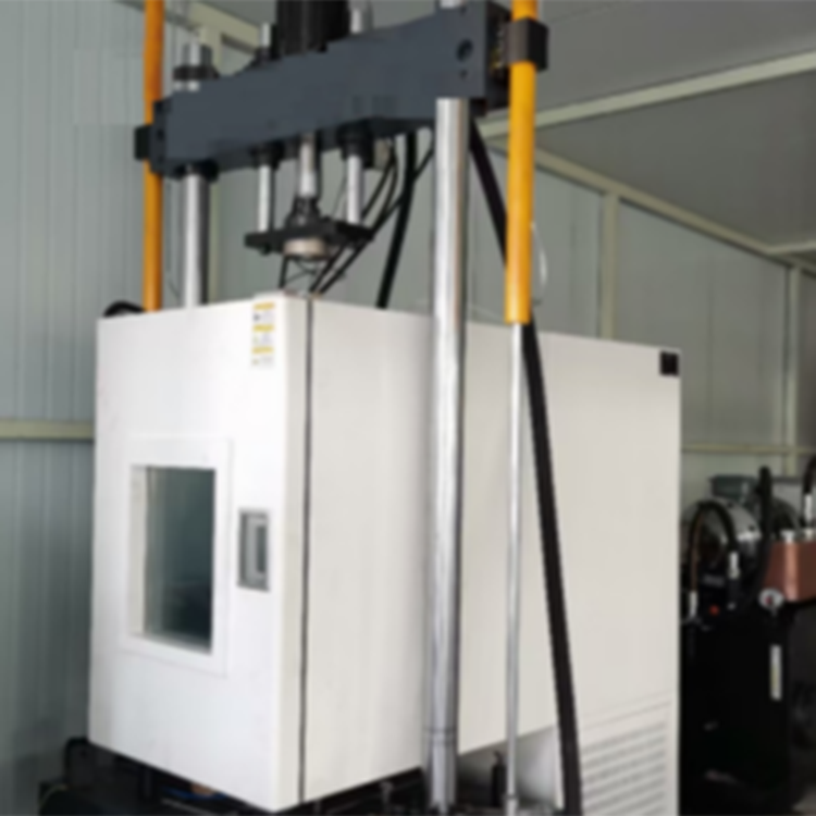
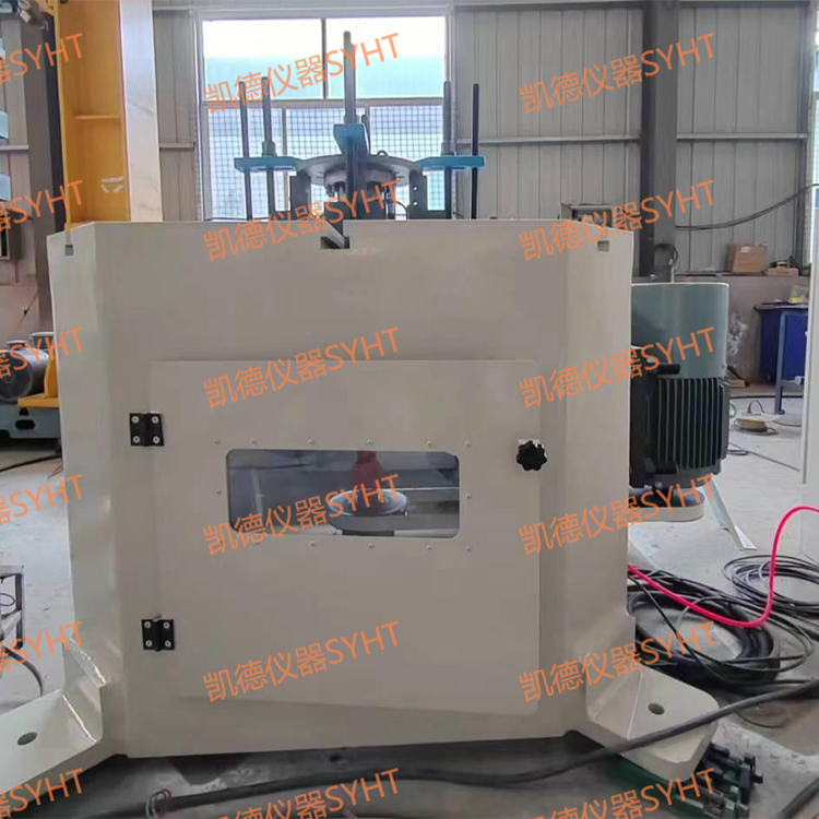
The testing machine is composed of a servo loading power unit with torque and angle measurement, a movable and adjustable bracket, a bed with an adjustable slide and protective device, connecting parts, a control computer, a printer, a control operation cabinet, and an operator's box.
● Power unit loading:
This unit is composed of a servo motor, reducer, driving bracket, angle sensor, mounting fixtures, and more. When torque and angular displacement output is required from this unit, the computer sends a command, the servo motor rotates, and by setting the torque and angular displacement, the output of both can be achieved. Simultaneously, the computer sends the measured torque and angular displacement to the computer via the A/D module. The entire sliding platform features manual control buttons for forward and backward movement, allowing manual locking at an appropriate position. The fixed swing angle can be manually adjusted.
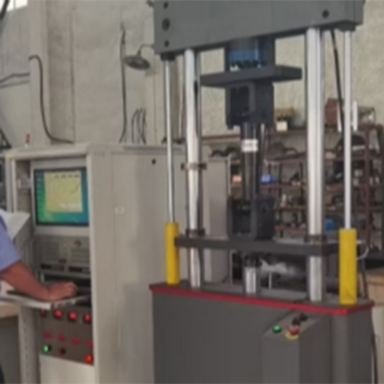
Computer Measurement and Control Systems:
The system consists of a servo controller, torque sensor, angle sensor, control computer, printer, and operating control cabinet.
Torque Measurement:
During the activation of the power device, it outputs a certain torque to the specimen. The torque sensor outputs different signals under different torques, and the computer measures this signal through the A/D conversion module, calculates, and displays the torque acting on the specimen at that time.
2) Corner Measurement:
As the power unit is activated, it drives the specimen to rotate. The angle sensor outputs different signals at various angles, and the computer calculates and displays the angle of rotation of the specimen based on the received signal.
3) Control System:
When the need arises to activate the power unit, the computer sends a command to the servo controller, which then controls the motor to rotate and twist the specimen through a reduction mechanism. This achieves torque and angular displacement output.
4) Utilizing Synetek Industrial Computers. The system runs on Windows operating system as per user requirement, and all peripheral device drivers are compatible with Windows. All accompanying software programs will be provided to the user upon completion of delivery.
III. Inspection Method:
1. Static torsional rigidity test
① Assemble the sample on the test bench according to the testing method.
Apply a pre-torque to the specimen in a specific direction, increasing the pre-torque until it reaches the rated load, then return it to the original state.
③ Apply torque in a certain direction for testing, increase torque to the rated load, then unload to zero load, and automatically record the torque and its corresponding torque angle.
④Record test results and calculate the constant-velocity universal joint's static torsional rigidity.
2. Static Torsion Strength Test
① Mount the sample on the test bench according to the testing method.
Apply a preliminary torque to the specimen in a specific direction, increasing it until it reaches the rated load, then return it to its original state.
③Apply torque in a specific direction for testing, automatically recording the torque and corresponding twist angle until the weak components of the constant-speed universal joint are damaged.
④Record test results and plot the torsion curve graph.
3. Adjustments of Distances Between Parts:
① Depending on the sample type, the slide table distance can be adjusted manually by using the hand control box to move the sample to the desired length, then manually lock it in place to mount the sample on the testing table.
Apply a preliminary torque to the specimen in a specific direction, increasing it until it reaches the rated load, then return it to its original state.
③Apply torque in a specific direction for testing, automatically record the torque and its corresponding twist angle until the weak components of the constant-speed universal joint are damaged.
④Record the test results and plot the torsion curve.
IV. Key Features:
1. Through computer control, achieve measurements of torque and torsional angle, control the operation, stop, forward, reverse of the workpiece, and perform stepless speed adjustment.
2. Test results are displayed on the computer screen, accompanied by corresponding working curves. The working interface is user-friendly, easy to observe and operate, and enables automatic control of the computer.
3. The transmission system employs high-reliability servo motors and reducers for smooth operation, while also reducing power loss.
V. Main Technical Specifications:
1. Torque ±10,000 N·m
2. Torque measurement accuracy ≤ ±1%
3. Twisted angle display range: n x 360°
4. Twist Angle Display Resolution: 0.01°
5. Speed range: 0.1° to 720°/minute (variable)
6. Control Methods: Angular, Torque
7. Directional Twisting: Forward and Reverse Directions
8. Tailstock Movement: Operated by a manual button, the RV motor reducer drives the screw to move forward and backward along the guide rail.
9. Jaws spacing: 100-1300mm
10. Horizontal Swing Angle: ±45° (Manual Adjustment)
11. Swivel Center Adjustment: The inner and outer ball sockets' swivel centers are adjusted by two separate screws, manually.
12. Connection Type: Flanged Disc
13. Equipment Geometric Dimensions: 3000×1320×1500mm (Length×Width×Height)