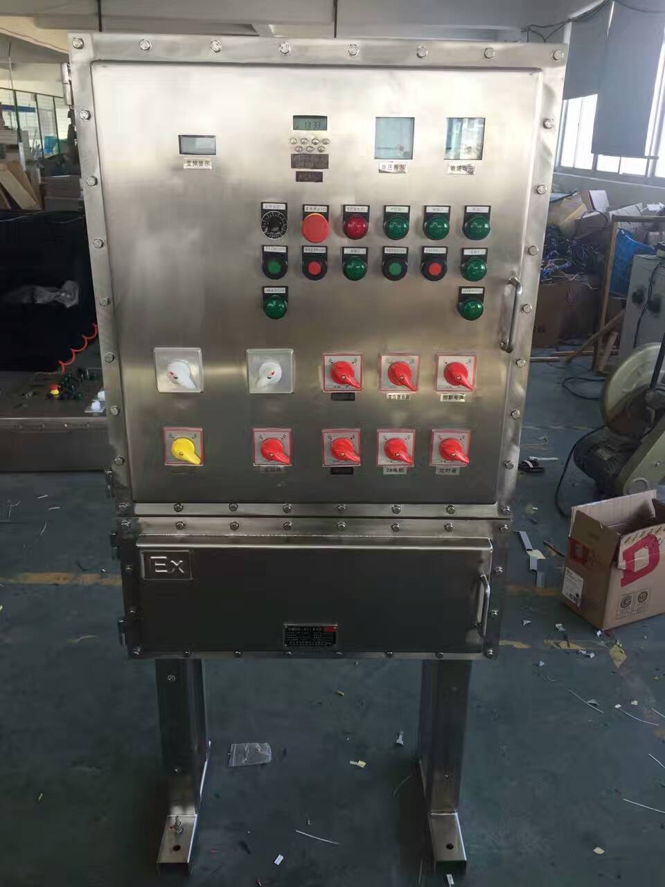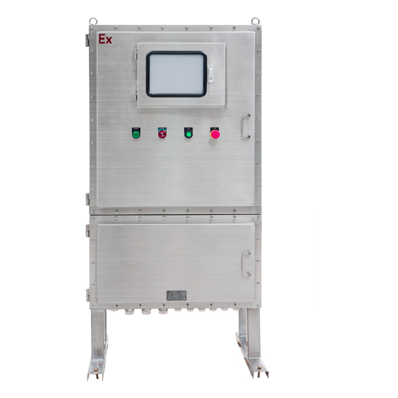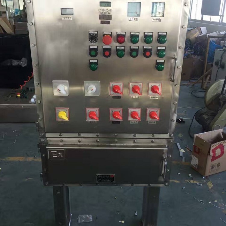


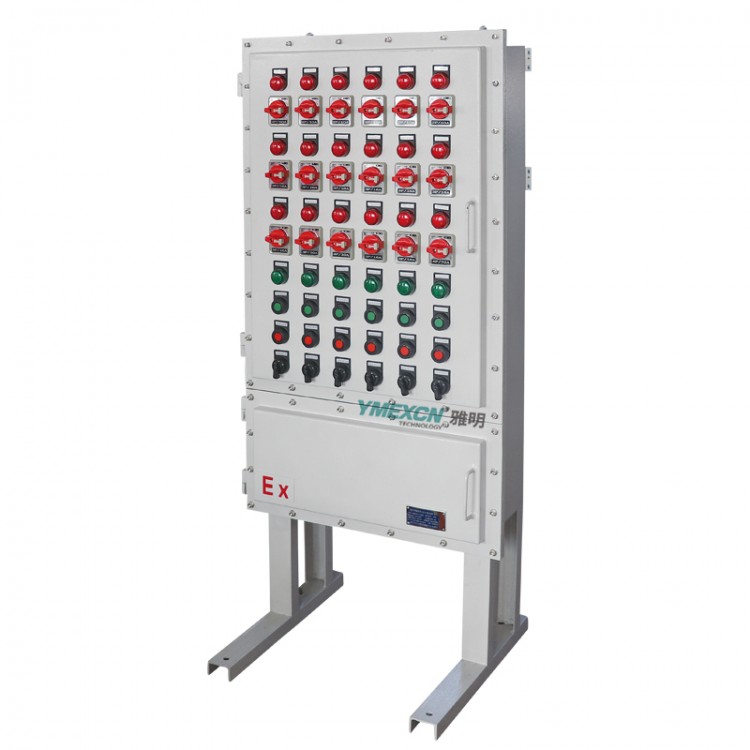
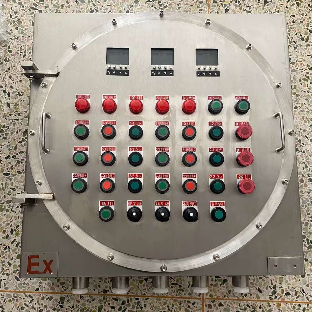
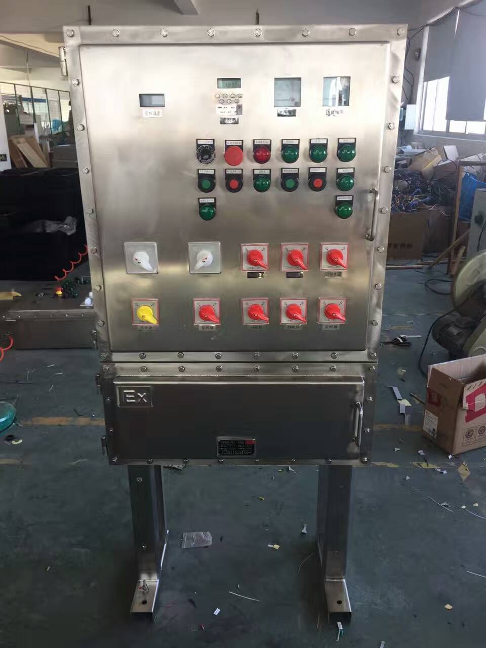
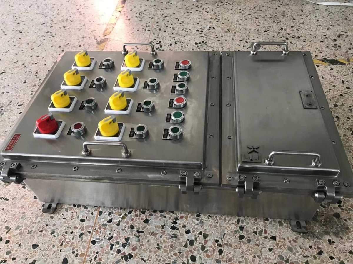
Stainless Steel Explosion-Proof Distribution Box, Explosion-Proof Control Box, Explosion-Proof Electrical Box

2.1 The materials used for electrical distribution boxes and cabinets must meet national standards. All distribution boxes and cabinets must be made of cold-rolled steel plates that comply with national standards. Floor-standing cabinets are made from 2.0mm thick cold-rolled steel plates. Lighting distribution boxes and control cabinets larger than or equal to 600mm use 2.0mm thick cold-rolled steel plates, while those smaller than 600mm use 1.5mm thick cold-rolled steel plates. The second floor base plate requires 2mm thick cold-rolled steel.
2.2, Drop-down lid for the landing cabinet, no knock-out hole for the electrical box.
2.3 The lighting box should be equipped with a two-layer door. The installation bolts between the second-layer bottom plate and the box body or cabinet should be no smaller than M5, and the overhanging edge of the second-layer bottom plate should be no less than 30mm from the bottom of the box.
2.4. (To be filled in) Distribution boxes are equipped with keyed locks, (To be filled in) cabinets use general-purpose locks, with each lock coming with two keys.
2.5 Metal parts of distribution boxes and cabinets: The installation plates, brackets, and metal casings of electrical appliances are all well grounded. Electrical appliances are installed on the doors and panels of the distribution boxes and cabinets, and can be connected to the grounded metal framework with bare copper flexible wires passing through transparent plastic tubes when opened.
2.6. For the box body with a thickness below 3mm, a 40×4 galvanized flat steel bar, running the full length, is attached to the left rear of the box body, with each end extending 15cm beyond the box. For box bodies with a thickness greater than 3mm, a 40×4 galvanized flat steel bar is welded to the top and bottom of the left rear of the box body (the welding length of the galvanized flat steel bar with the box body must meet the specifications). Each end extends 15cm beyond the box. In the middle of both the left and right sides of the box, 10cm from the top and bottom, an L40×4×50 angle steel bar is laid (for use in securing the box during installation).
2.7 Power distribution box models, cabinet materials, and colors are determined by the construction unit (with written signature records).
2.8 All distribution cabinets must be equipped with 10# base channel steel, with the outer diameter of the base channel steel matching the outer diameter of the bottom opening of the cabinet (when multiple cabinets are placed side by side, the 10# base channel steel should be a single unit).
2.9 When two or more distribution boxes/cabinets are installed adjacent to each other, their heights and thicknesses should be consistent. If the manufacturer is unsure, they may contact the construction party for confirmation.
2.10 In the power lighting distribution box, there must be reserved wire connection positions for the ground and neutral busbars, grounding bolts not less than M10, galvanized bolts, and the grounding point must be located in the lower left corner of the box.
3. Explosion-proof lighting distribution box components:
3.1 All molded-case circuit breakers and switch-disconnectors shall use (to be filled in) company products. Double-pole circuit breakers shall use (to be filled in) products. Manufacturers provide matching cable terminal blocks. If the incoming and outgoing cables are large, while the molded-case circuit breakers and switch-disconnectors have small terminals, a busbar should be installed to extend the terminals externally.
3.2 Power distribution boxes, electrical appliances, meters, etc., inside the cabinets, must undergo testing and electrical withstand voltage/current tests. If the electrical meters designed in the design drawings are to be installed by the power supply department, the power distribution cabinet should have a designated space for meter installation. No price adjustment after winning the bid (excluding the meter).
3.3 Other components, accessories, and materials must comply with the current national or industry technical standards.
3.4 Provide certificates of conformity and Chinese instructions for all components and wires (for products subject to mandatory certification, provide CCC certification certificates and CCC test reports). Provide import product supplier inspection proof.
3.5 Power distribution boxes, cabinets, and below operational and control components such as circuit breakers, indicator lights, buttons, and rotary switches must have a firmly attached label holder and machine-printed labels.
3.6 Electrical Components, specifications and models are shown in the system diagram (please note various control requirements such as building automation, fire protection, ventilators, night lighting, sewage pumps, and general design specifications). For unclear specifications, models, or control details, please contact the designer.
4. Explosion-proof lighting distribution box assembly line
4.1 Distribution boxes, electrical appliances on cabinets, and instruments should meet the requirements for spacing between electrical and instrument arrangements.
4.2 All fasteners are zinc-plated.
4.3 The secondary wiring all uses black wire, numbered with sleeves, and the wire diameter follows the manufacturer's standard.
4.4 Layered distribution box wiring should consider main line in and out.
4.5 The switch terminal should match the wire cross-section.
4.6 Power distribution boxes and cabinets equipped with metering instruments; if multi-core copper wires are used, they must be fitted with conduit or crimped with ferrules, and tin-plated properly.
4.7 The wiring after electrical installation must be neatly arranged, tied into bundles with nylon straps or laid in conduits, and securely fastened behind the panel or inside the cabinet mounting rack. Appropriate length of wiring should be left.
4.8 Power distribution boxes and cabinets, all types of switches and relays installed, when in the open position, moving parts should not be energized; vertically mounted, the top is connected to the power source, the bottom to the load; horizontally mounted, the left end is connected to the power source, the right end to the load. (Referring to the face of the power distribution unit)
4.9 Distribution boxes, cabinet power indicators, etc., should be connected on the front side of the main power switch.
4.10 The wiring inside the distribution box and cabinets must be color-coded according to the design drawings. The power busbars inside the distribution box and cabinets should have color-coded phase identification marks.
When placing an order, customers must specify the number of circuits in the distribution box, the corresponding current for each circuit, and the number of poles of the circuit breaker. If it includes a leakage function, please also note that; if it includes a main switch, please specify the current and pole number of the main switch, as well as the direction and specifications of the incoming and outgoing lines, along with the corresponding quantities.
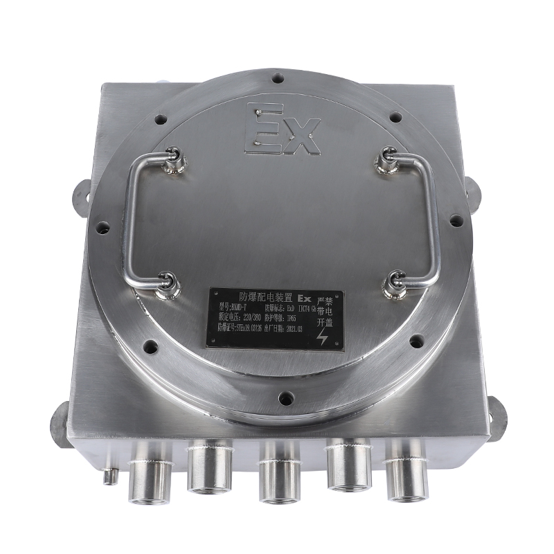
Model and Specification:BXMD-2/2K BXMD-3/3K BXMD-4/4K BXMD-5/5K BXMD-6/6K BXMD-7/7K BXMD-8/8K BXMD-9/9K BXMD-10/10K BXMD-12/12K
BXMD51-2/2K BXMD51-3/3K BXMD51-4/4K BXMD51-5/5K BXMD51-6/6K BXMD51-7/7K BXMD51-8/8K BXMD51-9/9K BXMD51-10/10K BXMD51-12/12K
BXMD52-2/2K BXMD52-3/3K BXMD52-4/4K BXMD52-5/5K BXMD52-6/6K BXMD52-7/7K BXMD52-8/8K BXMD52-9/9K BXMD52-10/10K BXMD52-12/12K
BXMD53-2/2K BXMD53-3/3K BXMD53-4/4K BXMD53-5/5K BXMD53-6/6K BXMD53-7/7K BXMD53-8/8K BXMD53-9/9K BXMD53-10/10K BXMD53-12/12K
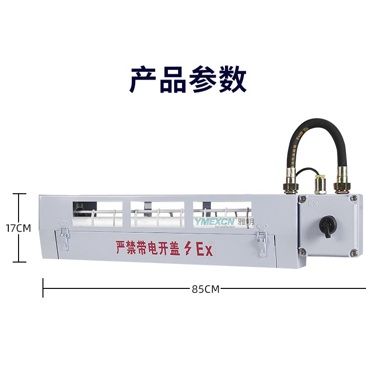
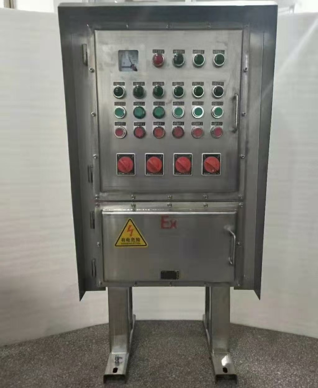
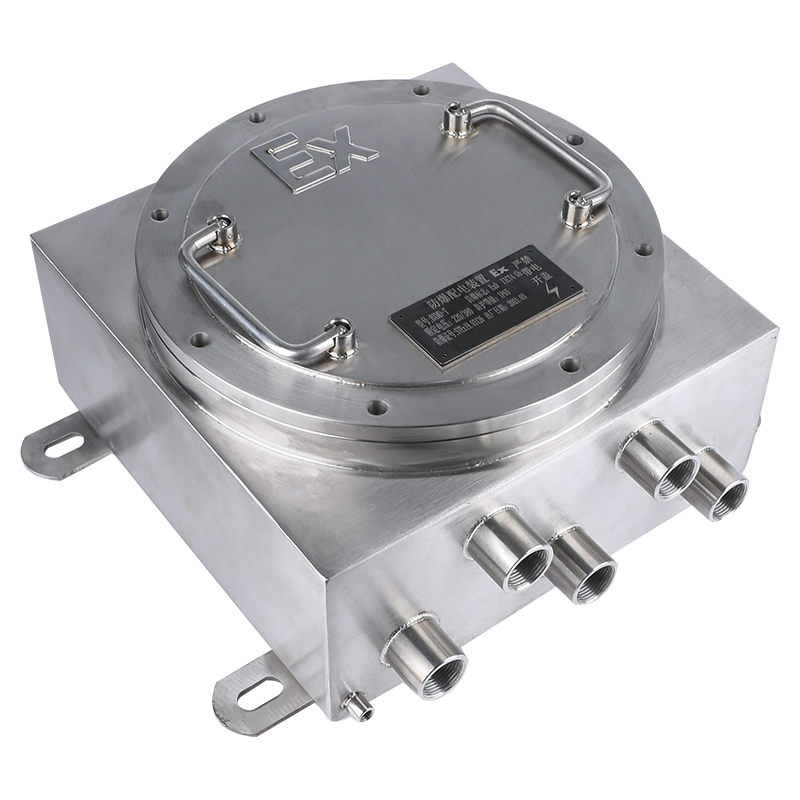
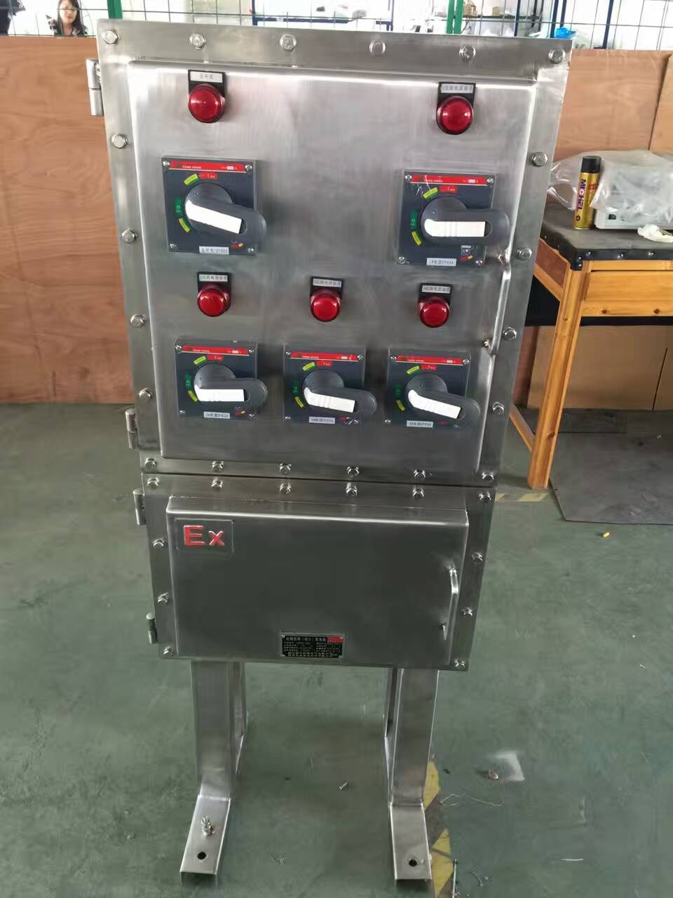
Optional power box: Die-cast aluminum housing/Steel plate/Stainless steel welding and molding, with powder coating surface. Features a main cavity and a wiring cavity, both with explosion-proof structures. High-interrupting circuit breakers, AC contactors, thermal relays, control buttons, signal lights, and other components are available for optional installation inside. Operation is achieved through handles on the shell cover, ensuring reliable performance with split and close indicators. Line entry and exit can be via steel pipe or cable wiring, with orientation and internal components customizable to user requirements. Other materials and appearances can also be customized according to user specifications.Branch circuit rated current:1A、3A、5A、10A、15A、20A、25A、32A、40A、50A、60A
Main Road Rated Current:20A、25A、32A、40A、50A、60A、80A、100A、125A、150A、160A、200A、250A
Sizes can be freely combined with components, and a rain cover can be added for outdoor use.