


I. Instrument Overview
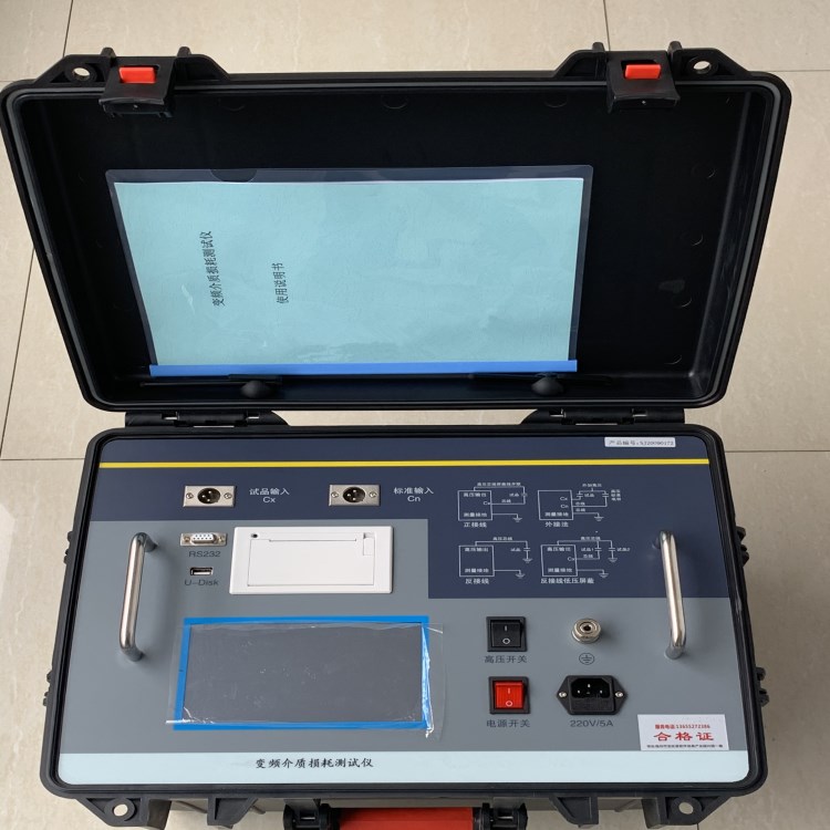
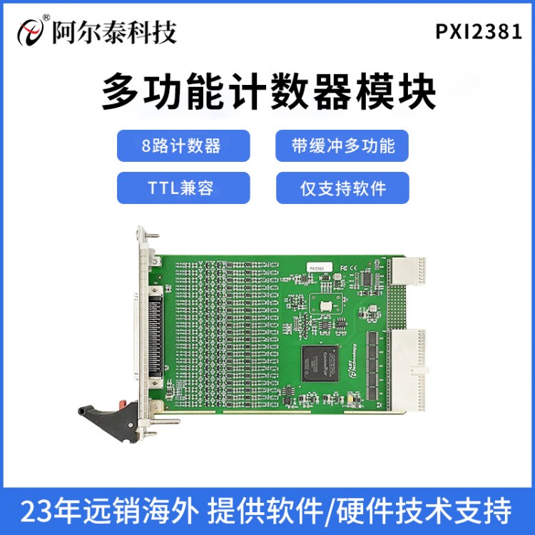
Dielectric loss measurement is a fundamental method in insulation testing, effectively detecting overall moisture deterioration and degradation, as well as local defects, in electrical equipment insulation. It is widely used in electrical manufacturing, equipment installation, handover, and preventive tests. The measurement of dielectric loss in transformers, current transformers, reactors, capacitors, and bushings, as well as lightning arresters, is a basic method to evaluate their insulation performance.Variable Frequency Medium Loss TesterBroken through the traditional bridge measurement method, adopting variable frequency power supply technology, utilizing single-chip microcomputers and modern electronic technology for automatic frequency conversion, model/Turn conversion and data calculation; features strong anti-interference capability, fast testing speed, high precision, fully automatic digital operation, and simple operation; powered by a high-power switching power supply, delivering pure sine waves at 45Hz and 55Hz, with automatic voltage increase and capable of providing up to 10 kilovolts of voltage; automatically filters out 50Hz interference, suitable for field testing in power stations and other locations with strong electromagnetic interference. Widely used in the power industry for measuring dielectric loss in transformers, current transformers, insulators, capacitors, surge arresters, and other equipment.
II. Safety Measures
Before using this instrument, please carefully read this manual.
2. Operators of the instrument should possess general knowledge of the use of electrical equipment or instruments.
3. This instrument can be used both indoors and outdoors, but should be avoided in places where it is exposed to rain, corrosive gases, excessive dust, high temperatures, and direct sunlight.
4、Gauges should be protected from severe vibration.
5. Maintenance, care, and adjustment of the instrument should be performed by personnel.
6. Prior to any wiring, the instrument's ground terminal must be securely connected to the earth using a grounding cable.
7. Due to the high voltage produced by the testing equipment, test personnel must strictly adhere to safety operating procedures at all times to prevent others from contacting high-voltage components and circuits. Individuals directly involved in testing must fully understand the high-voltage testing circuits and key points of instrument operation. Non-testing personnel must stay clear of the high-voltage testing area, which must be clearly marked with fences, ropes, warning signs, etc.
8. Adjustment, repair, and maintenance of the instrument must be conducted without power on. If power is necessary, the operator must be very familiar with the high-voltage hazardous components of this instrument.
9. When the fuse is damaged, it is mandatory to replace it with an identical fuse. It is strictly prohibited to replace it with a different model or to use the fuse in a direct short circuit.
10、If the instrument malfunctions, turn off the power switch and wait a minute before checking.
Section 3: Performance Features
1、The instrument employs Fourier Transform Digital Filtering technology to measure capacitance, dielectric loss, and other parameters. The test results are highly accurate and facilitate automated measurements.。
2. The instrument employs frequency conversion technology to eliminate 50Hz power frequency interference on-site, ensuring reliable data even in strong electromagnetic interference environments.
3. UtilizeFull-touch ultra-large LCD display, easy to operate. Full-touch LCD screen with a super-large graphical operation interface, each process is very clear and easy to understand, operators can use it without additional professional training. A light touch can complete the entire process measurement.
4、Data Storage: Equipped with a calendar chip and a large-capacity storage, it can save test results at any time and allows for easy viewing of historical records. Printing and output are also available. Current time and storage time can both be displayed and printed on demand.
5、Scientifically advanced data management: Instrument data can be processed throughUSB drive export, data can be viewed and managed on any PC with dedicated software.
6. The instrument is easy to operate, with the measurement process controlled by a microprocessor. Simply select the appropriate measurement method, and the data measurement can be automatically completed under microprocessor control.
7. Integrated model with standard capacitors and high-voltage power supply included, convenient for on-site testing and minimizes on-site wiring.
8. The instrument boasts high measurement accuracy, capable of meeting oil interfacial loss measurement requirements. Thus, only standard oil cups and testing cables are needed to carry out oil interfacial loss measurement.
9. Reverse-wiring low-voltage shielding function。
10、AvailablePerform dielectric withstand test. Convenient.PT and CT undergo secondary dielectric withstand tests; 400V low-voltage system for withstand voltage testing.
11AvailableIdentify the frequency of the external high-voltage power supply40Hz~70Hz, allows for using power frequency or series resonance power supplies for large capacity high voltage dielectric loss tests.
12Self-contained thermal printer with print output, featuring a calendar clockFor easy test report generation, comes with USB drive output.
13With computer interface. One computer can control 32 instruments, capable of being integrated into a comprehensive high-voltage test vehicle for measurement, data processing, and report generation.
14Grounding protection function: If the instrument is not properly grounded or the grounding is poor, the instrument will not enter the normal program and will not output high voltage. Overcurrent protection function: The instrument will not be damaged in case of sample short circuit or breakdown.
15Electrical shock protection feature: In case the operator of the instrument accidentally gets electrocuted, the instrument will immediately cut off the high voltage, ensuring the safety of the test personnel..
Section 4: Technical Specifications
Accuracy: Cx: ±(reading × 1% + 1pF)
tgδ: ± (Reading x 1% + 0.00040)
Interference Resistance Index: Frequency conversion with anti-interferenceAchieve the aforementioned accuracy even under 200% interference.
Capacity Range: Internal high voltage: 3pF~60000pF/10kV 60pF~1μF/0.5kV
Apply External High Voltage: 3pF~1.5μF/10kV 60pF~30μF/0.5kV
Resolution:*High0.001pF, 4 significant figures
TGδ Range: Unrestricted, resolution0.001%, automatic identification of capacitors, inductors, and resistors.
Test Current Range:5μA~5A
Internal High Voltage: Set Voltage Range:0.5~10kV
High Output Current200mA
Lifting and lowering method:Voltage can be set at will. For instance:5123V。
Test Frequency: 40-70Hz single frequency can be freely set. For example, 48.7Hz..
50±0.1Hz to 50±10Hz automatic dual-frequency, freely adjustable.
60±0.1Hz to 60±10Hz automatic dual-frequency, freely adjustable.
Frequency Accuracy: ±0.01Hz
External high voltage application: During normal wiring, *maximum test current5A, 40-70 Hz, power or variable frequency
Reversing wiring *maximum test current10kV/5A, 40-70 Hz AC or Variable Frequency
Input Power: 180V~270VAC, 50Hz±1%, Mains or generator power
Computer Interface: StandardRS-232 Interface,USB port (for automatic USB data storage).
Printer: MiniThermochromicPrinter Ambient Temperature:-10℃~50℃ Relative Humidity: <90%
Dimensions:500mm*377mm*330mm Instrument Weight:28kg