


Safe Operation
• If not in a laboratory setting, the testing instrument must be securely grounded before use. The grounding point should be as close as possible to the test object.
• Always disconnect cable connections starting from the power transmission device.
• Do not connect or disconnect the test object when the device is outputting. External inductive stored energy may cause lethal high voltage.
• During testing, always keep one terminal of the transformer's high-voltage side grounded.
• Do not insert other objects into the ventilation orifice or input./ Export goods.
• Before inserting the tester into operation, inspect for any visible damage.
• Do not operate the tester in rainy or humid climates.
• Do not operate the tester in an environment where explosive gases or vapors are present.
• Before operating the tester, ensure that the ventilation openings, power switch, and power outlet are not blocked.
• The internal of the tester may generate high voltage! Therefore, only qualified personnel are permitted to open the test instrument.
• To prevent parasitic current or voltage, always connect the test instrument's equipotential ground to the protective ground.
• Ensure the terminals of the test object connected to the tester are at zero potential. During the test, the tester is the permissible power supply for the test object.
• When measuring the ratio of the transformer, ensure proper wiring; otherwise, life-threatening voltages may be generated internally, and the transformer connected to the tester may be damaged!
• Input on the panel/ The wiring for the output port must be done with a cable that has4 mm2 SafetyCable with a banana plug and plastic housing.
• Do not stand under or near the connection head, as clamps may fall and injure you.
• If the tester or any additional devices or accessories appear to be malfunctioning, please discontinue use.
Note:
For personal and equipment safety, please read the instructions carefully before use and operate strictly according to the requirements.
2. Please securely ground the instrument prior to testing.
3. This tester isTransformer Offline TestingEnsure that the connection wires at each terminal of the transformer are properly disconnected during all tests on the transformer.Open.
4. During the CT ratio and polarity test, the secondary winding that is not to be tested should be short-circuited.
5、Please provide the Chinese content that needs to be translated into American English.During the PT伏安特性试验, the zero terminal of one winding is grounded.
6. Absolutely no contact with any test terminals is permitted during the experiment.
This company reserves the right to modify this manual. In case of discrepancies between the product and the manual, the actual product shall be the standard.
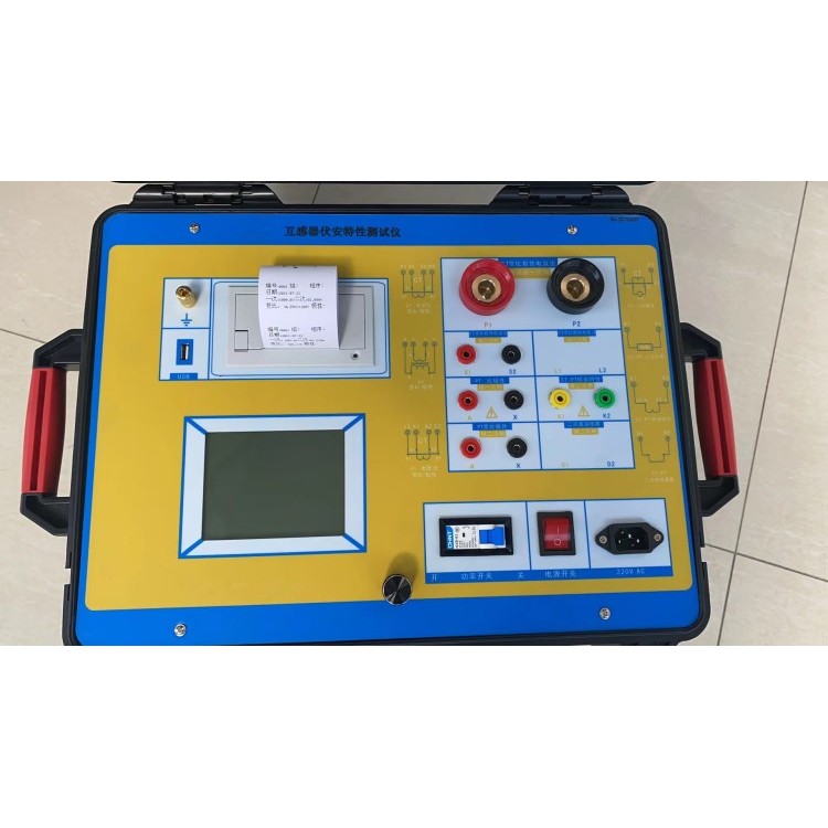
1.Design Purpose
Designed for protective and measuring applicationsCT/PTConduct automated testing, suitable for both laboratory and on-site inspections.
2.Reference Standards
GB 1207-2006、GB 1208-2006
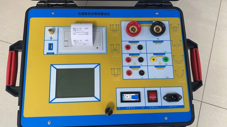
3.Key Features
• Support for inspectionsCTAndPT
• Satisfy GB1207、GB1208 and other regulations.
• No external auxiliary equipment required; all testing items can be completed on a single machine..
• Built-in mini rapid printer, capable of printing test results on-site directly.
• Equipped with an intelligent controller, operation is simple..
• Large-screen LCD, graphical display interface.
• Automatically provided according to proceduresCT/PT(ExcitationInflection Point.
• Automatically Provided5%And10%Error Curve.
• Saveable3000Compile test materials; data not lost after power failure.
• SupportURotate and save data, via standardPCPerform reading.GenerateWORD Report.
• Compact and lightweight≤22Kg, veryBeneficial for on-site testing.
4.Main Test Function of the Tester:(See table)1)
CT | PT |
• V-I Curve (Excitation Curve) | • V-I Characteristics (Excitation Characteristics) Curve |
• Automatically provide inflection points | • Automatically provide inflection points |
• Automatically generated5%And10%Error Curve | • Ratio Measurement |
• Ratio Measurement | • Polarity Determination |
• Polarity Determination | • Difference measurement |
• One flow test | • Phase (Angular Difference) Measurement |
• Difference measurement | • Communication Pressure Test |
• Phase (Angular Difference) Measurement | • Iron core demagnetization |
• Communication Pressure Test | |
• Core demagnetization |
Table1
5. Main Technical Parameters of the Tester: (See Table)2)
Item Objective | Please provide the Chinese content to be translated. Numbers | |
Working Power Supply | AC220V±10% 、50Hz | |
Equipment Output | 0~1000V(20APeak) | |
High Current Output | 0~600A | |
ExcitationMeasurement Accuracy | ≤0.5%(0.2%*Reading+0.3%*Range | |
Phase Measurement Corner difference | Accuracy | 4min |
Resolution | 0.1min | |
Competitive pricing | Accuracy | 0.05% |
CT Ratio Measurement | Scope | ≤5000A/1A(25000A/5A) |
Accuracy | ≤0.5% | |
PT Ratio Measurement | Scope | ≤500KV |
Accuracy | ≤0.5% | |
Work Environment | Temperature:-10℃ ~40°C, Humidity:≤90%Altitude:≤1000m | |
Dimensions, weight | Dimensions:410mm × 260mm × 340mm , Weight:≤22Kg | |