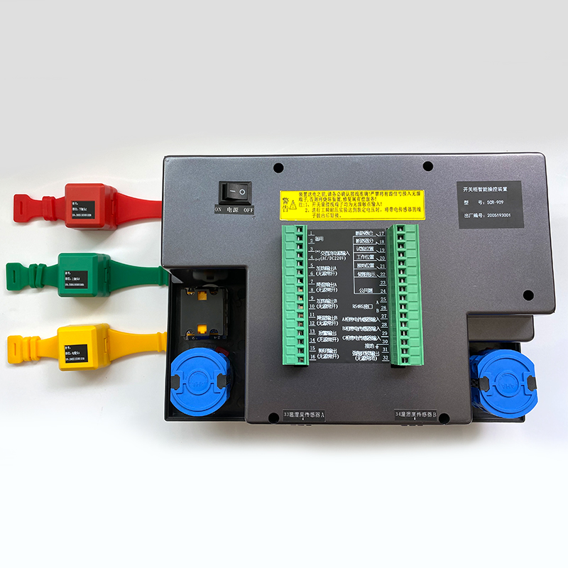


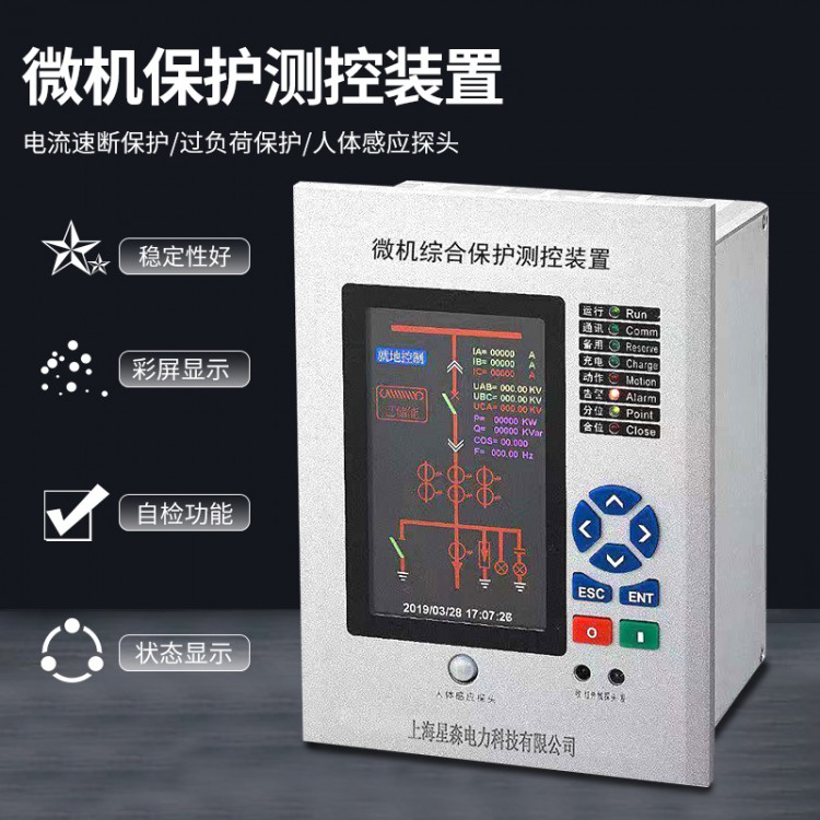
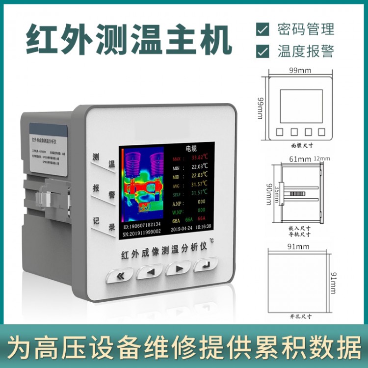
The device can simultaneously measure the temperature of multiple electrical junctions. When the measured temperature exceeds the alarm threshold, the device outputs an alarm signal. Each operating and display device is equipped with standard accessories.3~9-point temperature sensing (receiving temperatures from 21 measurement points).
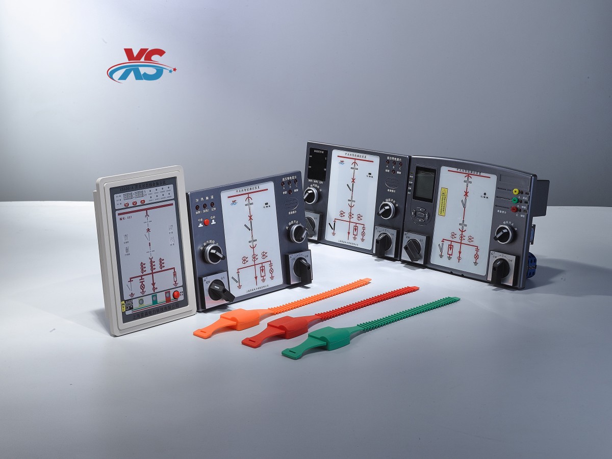
The electrical contact online temperature measurement system consists of an intelligent switchgear control device, contact temperature sensors, a temperature receiving module (already assembled in the control device), and an optional management software (not included).
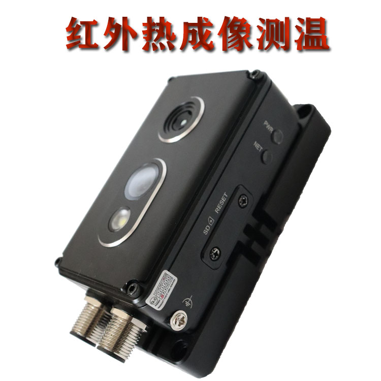
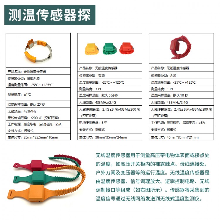
Wireless Temperature Sensor
Wireless temperature sensors are used to measure the temperature on the surface or at the contacts of high-voltage, live objects, such as exposed contacts inside high-voltage switchgear, busbar connections, outdoor switchgear, transformers, and more, to monitor their operating temperatures. The wireless temperature sensor consists of a temperature sensor, signal conditioning amplifier, logic control circuit, and wireless modulation interface (as shown in the diagram below). The sensor transmits the collected temperature signals to the wireless temperature monitor via a wireless network.
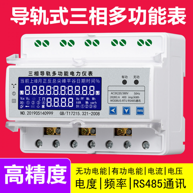
Power parameter measurement function
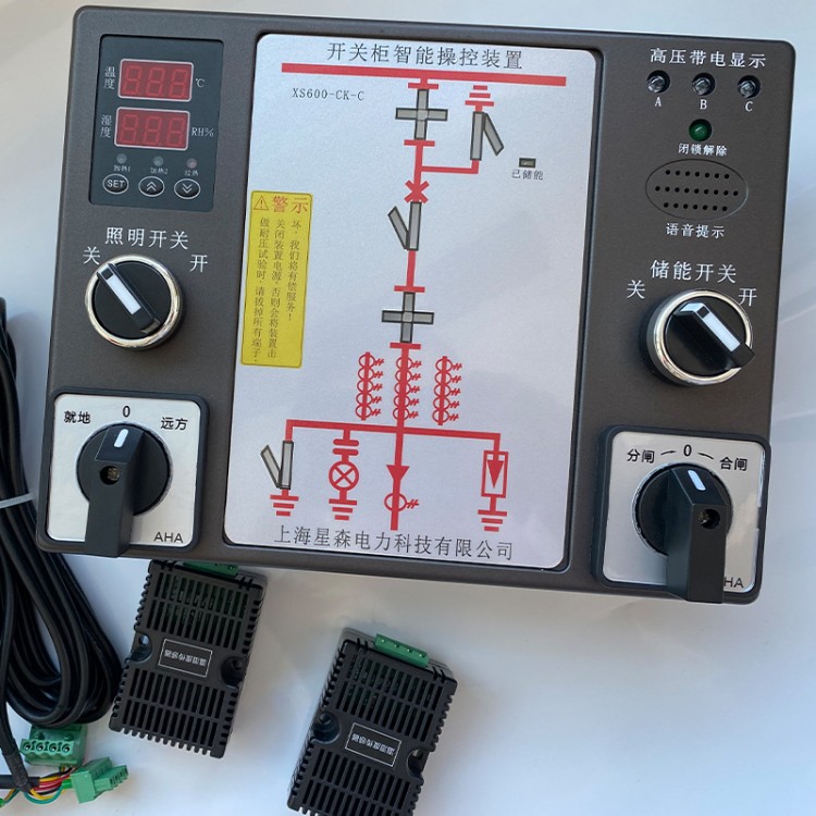
This unit is an intelligent operation and display device for a high-voltage switchgear, integrated with the functions of a three-phase multi-functional electric power meter. It can measure the active power of each phase in both forward and reverse directions, as well as the reactive power of both inductive and capacitive types. It also displays the current, voltage, active power, reactive power, and combined active and reactive powers for each phase. All performance indicators comply withGB/T 17883 "0.2S and 0.5S Class Static AC Active Energy Meters" and DL/T 614 "Multi-functional Energy Meters" standards outline the technical requirements for multi-functional energy meters. This series features a 100-year calendar, RS485 communication interface, offering stable performance, high accuracy, and easy operation, making it an ideal meter for modern energy management.
4.7.1 Measurement
The measuring functions provided by this device fully meet the requirements for measuring electrical parameters in high-voltage or low-voltage three-phase power networks. The measuring parameters offered by the instrument are as listed in the table below:
Measurement Parameters | Visible Please provide the Chinese content you would like translated into American English. | Please provide the Chinese content to be translated. Message | |
Variable Effective Value | |||
Electricity Pressure | Phase Voltage and Line Voltage | Primary and secondary sides optional | Secondary Side Value |
Electricity Flow | Single-phase and neutral wire | Primary and secondary sides optional | Secondary Side Value |
Effective Power | Single-phase and total | Primary and secondary sides optional | Secondary Side Value |
No-load power | Single-phase and total | Primary and secondary sides optional | Secondary Side Value |
Power Factor | Single-phase and Total | Secondary Side Value | One-side value |
Frequency Rate | One-time value | One-time value | |
Electricity Available | |||
Functional Power | Input and Output (can be measured separately) | One-time side value | Secondary side value |
No-load power | Sensorial and capacitive (can be measured separately) | Once-side value | Secondary Side Value |
4.7.2 Voltage Measurement
The device measures voltages belowAt 300V (phase)/520V (line), it can be directly connected without an external PT; otherwise, an external PT is required. When using an external PT, pay attention to the linearity and accuracy grade of the PT, as this may affect the overall measurement accuracy of the instrument.
The overload capacity of the voltage measurement channel for this device is typically up to the rated voltage.1.3 times, users should note this when designing to prevent the internal measurement circuit from becoming saturated, which can lead to inaccurate measurements.
4.7.3 Current Measurement
The overload capacity of the current measurement channel of this device is generally equal to the rated measurement current.1.3x, users should be aware of this during design to prevent the internal measurement loop from saturating, which could lead to inaccurate measurements.
4.7.4 Power Rating
Calculate three-phase active powerPa, Pb, Pc, and Total Active Power
4.7.5 Reactive Power
Calculate three-phase reactive powerQa, Qb, Qc, and total reactive power. Active and reactive power are signed variables; users should be aware of this when querying active and reactive power.
Note Note! |
When making connections, users should pay attention to the phase relationship between voltage and current; otherwise, it may cause errors in calculation data, and also noteCT's identical terminal wiring relationship; otherwise, it may result in negative power calculation data. |
4.7.6 Power Factor
Modified DeviceThe equipment can measure the power factor of each phase as well as the total power factor, with a measurement range of:-1.00 to +1.00, just like the power data, the corresponding relationship of wiring and the CT's same-name terminal will affect the actual calculated value of power factor.
4.7.7 Frequency
The device operates with different measurement modes, and the acquisition channels for frequency measurement vary accordingly. In the triangular mode, the device defaults to...AB line voltage channel frequency measurement; in other modes, the device measures frequency through the A phase voltage channel. If phase A is missing, it takes B; if both A and B are missing, it takes C.
4.7.8 Electric Energy Metering FunctionMetering Categories: Forward Active Energy, Reverse Active EnergyReactive power, capacitive reactive power.
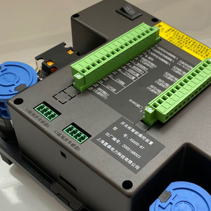
4.8 Communication Function
Equipped with standardRS485 Communication Interface (Modbus protocol, baud rates available in options of 1200, 2400, 4800, 9600).