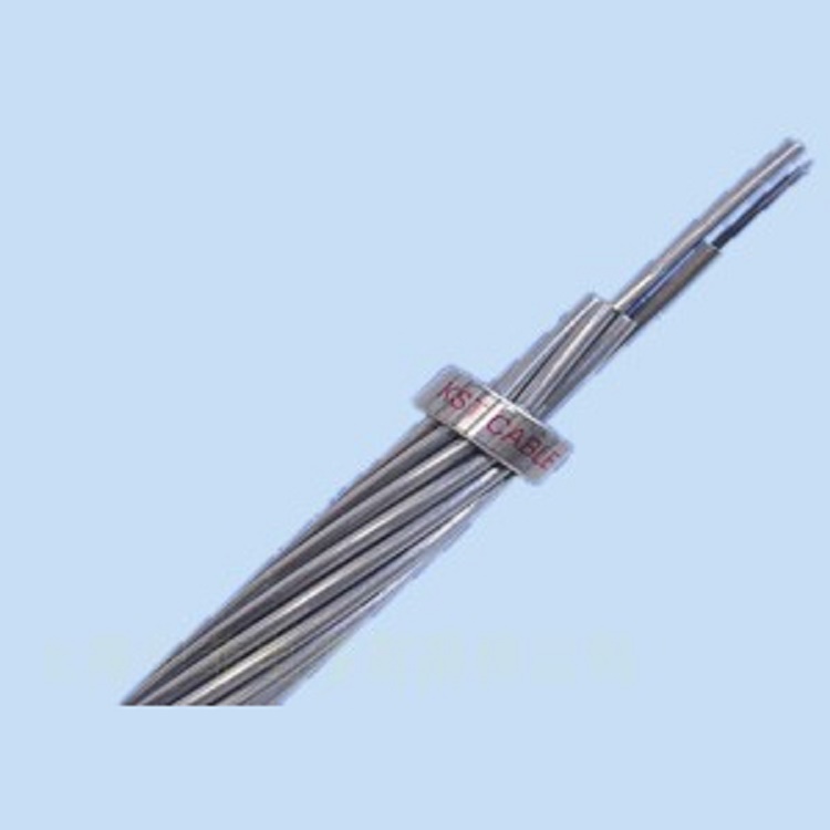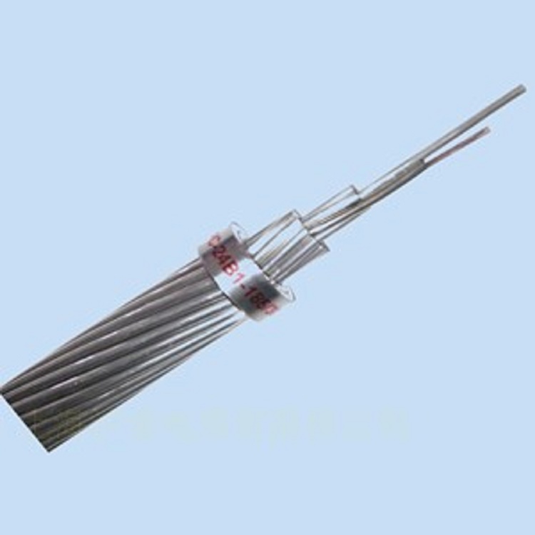


OPGW Optical Fiber Composite Overhead Ground Wire (also known as Fiber Composite Overhead Ground Wire). Placing optical fibers within the ground wire of overhead high-voltage transmission lines to form an optical communication network along the transmission lines. This structure combines the dual functions of grounding and communication, commonly referred to as OPGW optical cable.
Technical Specifications of OPGW
2.1 OPGW Structural Parameters
Total core length requirement: The excess length after cabling should be greater than 0.6%. Core color chart is shown in the attached table.
2.2 Fiber Optic Technical Specifications
G.652 optical fiber
Decay | |
1310nm(dB/Km) | ≤0.35 (after cabling) |
1550nm(dB/Km) | ≤0.22 (after cable assembly) |
Attenuation within the 1285-1330 nm range compared to 1310 nm (dB/Km) | ≤0.05 |
Attenuation within the range of 1480-1580 compared to 1550 (dB/Km) | ≤0.05 |
OH Absorption Peak (1383±3) Attenuation (dB/Km) | ≤2.0 |
1310 and 1550 attenuation discontinuity (dB) | ≤0.10 |
1310 and 1550 attenuation non-uniformity (dB) | ≤0.050 |
End-to-End Attenuation Difference (dB/Km) | ≤0.015(1310) |
≤0.015(1550) | |
Attenuation values (from -60℃ to +85℃; -10℃ to +80℃ RH 95%; 23℃ immersion; 85℃ aging) (dB/Km) | |
1310nm(dB) | ≤0.05 |
1550nm(dB) | ≤0.05 |
Model Field Diameter | |
1310nm(μm) | 9.2±0.5 |
1550nm(μm) | 10.4±1.0 |
Cutoff Wavelength | |
Cut-off Wavelength of Fiber (nm) | 1100~1330 |
Cable Cut-off Wavelength (nm) | ≤1260 |
Dispersion (ps/nm·km) | |
1285~1339nm(ps/nm.km) | ≤3.5 |
1270~1360nm(ps/nm.km) | ≤5.3 |
1550nm(ps/nm.km) | ≤17 |
Zero chromatic dispersion wavelength (nm) | 1300~1322 |
Zero-dispersion slope ps/(nm².km) | ≤0.092 |
Single-mode Fiber Polarization Mode Dispersion (ps/(km)1/2) | ≤0.10 |
Geometric characteristics | |
Coating Diameter (μm) | 125±1.0 |
Core/Cladding同心度误差(μm) | ≤0.5 |
Coating Roundness (%) | ≤1 |
Coating Diameter (μm) | 245±5 |
Coating/Sheath Concentricity Error (μm) | ≤12 |
Mechanical properties | |
Screening Test (%) | 1.0 (equivalent to 0.7 GPa) |
Fiber Coiling Radius (M) | ≥4 |
Macro-bend Attenuation | |
After winding 100 turns, attenuation change (dB) | ≤0.1(1550nm) Φ60 |
≤0.05(1310nm) Φ60 | |
Attenuation change after wrapping around once (dB) | ≤0.5(1550nm) Φ32 |
/ | |
Other Performance | |
Dynamic Fatigue Parameters (Nd) | >20 |
Appearance | Tightly arranged, vivid colors, durable and glossy coating, no peeling. |
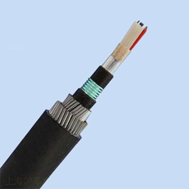
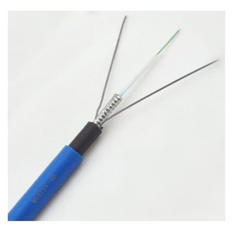
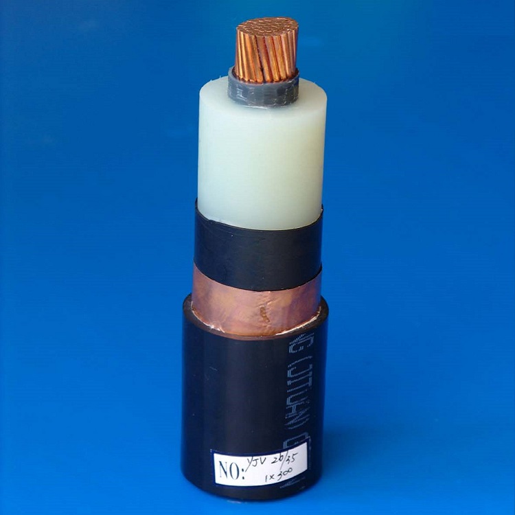
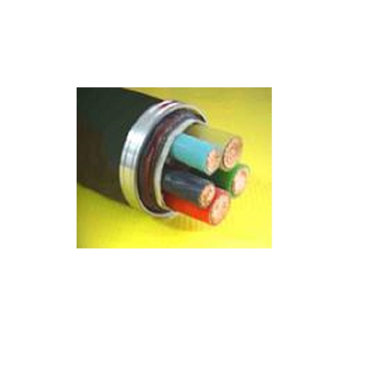
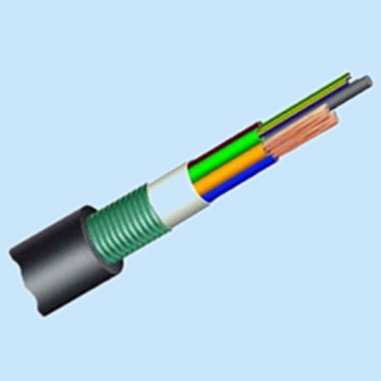
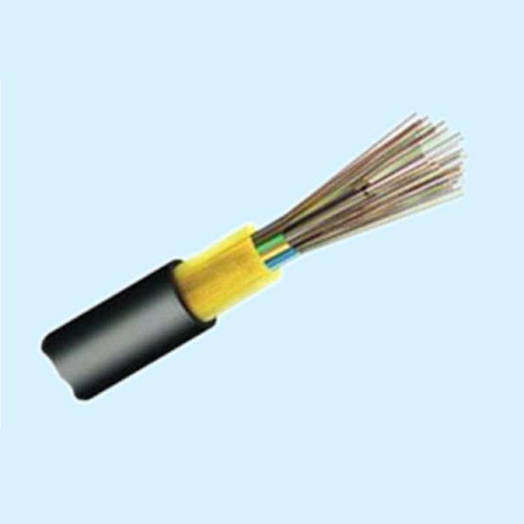
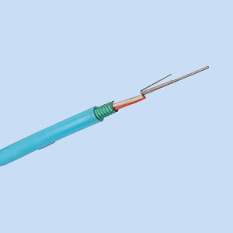
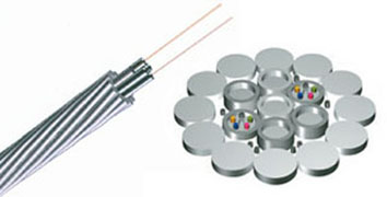
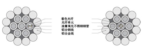
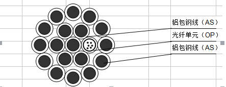
OPGW Cable Structure Diagram
Fiber Optic Cable Installation Design
Edit the installation design of the OPGW, considering the coordination with conductor stress, sag, and insulation gap, and ensuring that the load does not exceed the allowable usage range of the existing towers and foundations. Therefore, the characteristic curve of the selected OPGW should be calculated based on its main technical parameters, and combined with the actual engineering design of junction boxes, various hardware layouts, exterior views, and installation diagrams. 1. Initial elongation treatment: The initial elongation of OPGW can be handled by cooling method, i.e., by reviewing the aluminum to steel ratio of OPGW and treating its initial elongation based on the cooling values of similar conductors or ground wires. 2. Vibration prevention measures The hardware used with OPGW, including tension clamp and suspension clamp with pre-stressed wire and rubber pads, already have certain vibration prevention capabilities. To further enhance vibration prevention, consider installing vibration dampers, typically calculated as follows: install one vibration damper for spans ≤ 300M; install two vibration dampers for spans > 300M. 3. Issues to be aware of during OPGW construction The construction of OPGW is different from that of ordinary steel strand, and it is crucial to prevent damage to avoid future impact on the performance of the fiber. Pay particular attention to: OPGW twisting, minor bending, local radial pressure outside the clamps, and contamination to the fiber. Therefore, effective measures should be taken during the construction phase to address these issues: (1) Preventing OPGW twisting: Add balancing weights and anti-twist devices to the walking board and tension clamps; use special double-slot pulleys; employ a tensioning line machine with double winches; (2) Preventing and reducing minor bending and stress: No sharp angles are allowed (control bending radius to 500mm); the diameter of the OPGW drum should be no less than 1500mm; the pulley diameter should be more than 25 times the OPGW diameter, generally not less than 500mm; the inner side of the pulley should have nylon or rubber lining to prevent surface damage to the OPGW; use appropriate traction and laying hardware; specify the OPGW drum length as 6000M to prevent excessive passes over the pulley; limit continuous laying line angle to ≤30°, and the direction of the OPGW after turning should be in a "C" shape within a tensioned laying section; (3) Controlling laying tension: Use hydraulic tensioning line machines and traction machines with tension release devices; limit laying speed to ≤0.5 meters/second; (4) Preventing fiber contamination: Pay attention to encapsulating the ends during OPGW construction; in addition, perform fiber attenuation acceptance tests on-site promptly after the arrival of OPGW at the site, before and after installation, and after the completion of the entire construction.