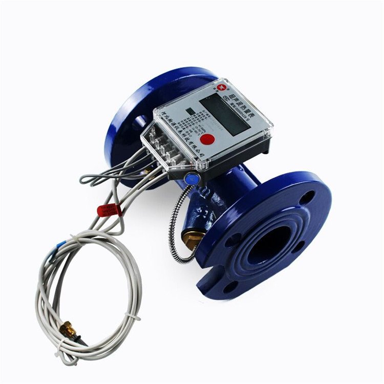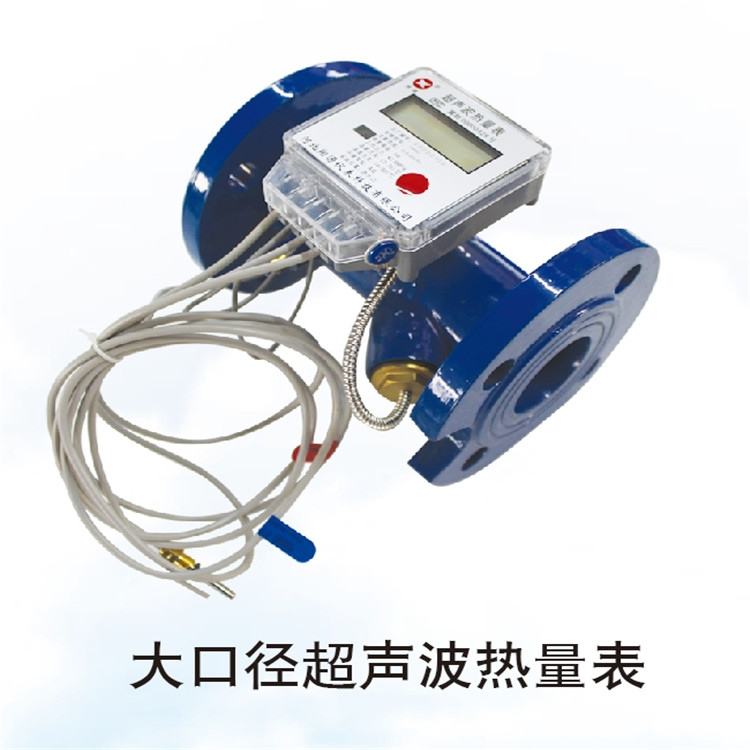

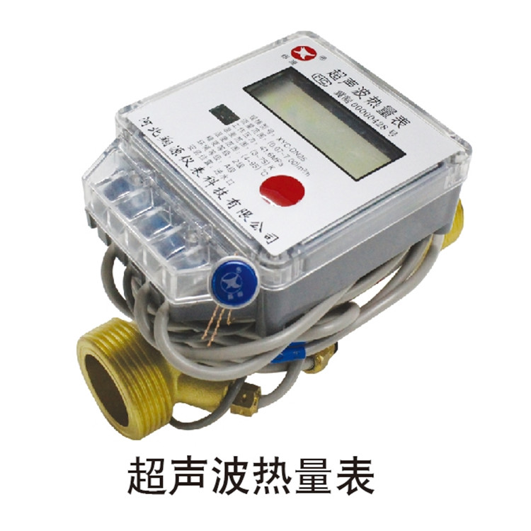


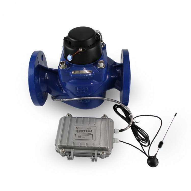

The ultrasonic heat meter is composed of a flow sensor, a matching temperature sensor, and a calculator, featuring a compact structure and easy installation.
Our products utilize ceramic piezoelectric transducers, ensuring high accuracy and stability; with no mechanical movement, no wear, and resistance to poor water quality, as well as low maintenance costs; they can be installed horizontally or vertically, and can be placed on the inlet or return piping according to user needs (preselection required); RS485 interfaces can be added upon customer request to enable remote meter reading functions according to different requirements, facilitating centralized management.
Nominal Bore Size (mm) | Traffic | Common Traffic | Traffic | Table body length |
m3/h | m3/h | m3/h | mm | |
DN15 | 0.03 | 1.5 | 3 | 110 |
DN20 | 0.05 | 2.5 | 5 | 130 |
DN25 | 0.07 | 3.5 | 7 | 160 |
DN32 | 0.12 | 6 | 12 | 180 |
DN40 | 0.2 | 10 | 20 | 200 |
DN50 | 0.6 | 15 | 30 | 200 |
DN65 | 1 | 25 | 50 | 200 |
DN80 | 1.6 | 40 | 80 | 225 |
DN100 | 2.4 | 60 | 120 | 250 |
DN125 | 4 | 100 | 200 | 250 |
DN150 | 6 | 150 | 300 | 300 |
DN200 | 10 | 250 | 500 | 350 |
DN250 | 16 | 400 | 800 | 450 |
DN300 | 24 | 600 | 1200 | 500 |
Water Flow Reading (m³) | 999999.99 | |||
Heat Reading (kW·h) | 99999999 | |||
Accuracy Grade | 2nd Grade | |||
Pressure loss | <25 kPa (at operating flow) | |||
Work pressure | 1.6MPa | |||
Heat consumption calculation | Starting from 0.25K | |||
Temperature Range | (4~95)℃ | |||
Temperature range | (3~75)K | |||
Temperature Resolution | 0.01℃ | |||
Environmental Grade | Type A (5-55)°C | |||
Battery Operating Time | ≥6 years (Lithium-ion Batteries) | |||
Temperature Sensor | PT1000 Platinum Resistance | |||
Communication Mode | Infrared; M-Bus; RS-485 (optional) | |||
The heat meter must be installed in a dry, accessible location.
2. Install the heat meter using professional installation tools.
3. The heat meter must be installed according to the instructions on the label (horizontal/vertical), with the text facing up, and the arrow direction on the meter body (including the filter) aligned with the flow direction of the HVAC piping. The outlet should be higher than the heat meter; when installed vertically, the flow direction must be upwards.
4. Ensure that new piping is thoroughly cleaned of debris such as stones, sand, and fibers before installing the heat meter to prevent malfunctions; according to the individual heating metering design requirements, a filter must be installed before the heat meter's inlet; the filter must be cleaned and maintained regularly.
5. To achieve measurement accuracy, leave a straight pipe section of approximately 10D length at the heat meter's inlet, where D is the heat meter's pipe diameter. The straight section at the front end of the outlet should not be less than 5 times the pipe diameter. When installed at the confluence of two return water pipelines, the heat meter's connection head (such as a T-joint) requires a straight pipe section of 10 times the pipe diameter to ensure uniform mixing of water temperatures between the two pipelines.
6. Data is collected from the heat meter via M-Bus bus. Do not connect this wire to the municipal power supply; otherwise, it may damage the meter.
7. The heat meter has a 485 interface at the top row; please note the polarity of the A and B lines when wiring.