


Material
Air Header: Carbon Steel, 304 Stainless Steel, Galvanized Steel Pipe
Air pipe: Carbon steel, 304 Stainless Steel, Galvanized steel pipe
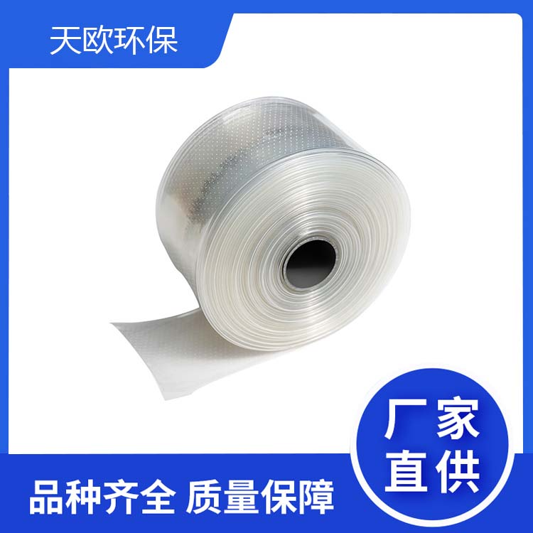
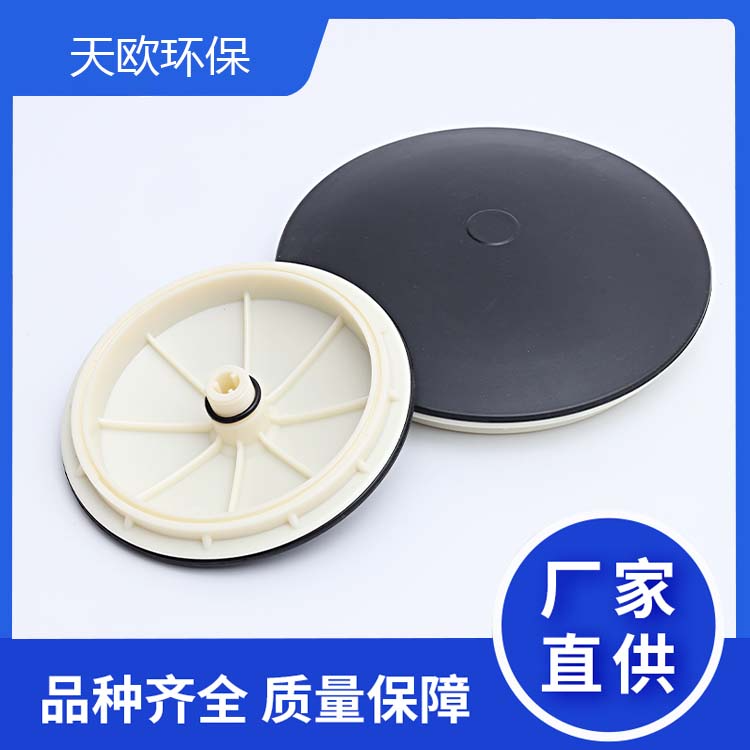
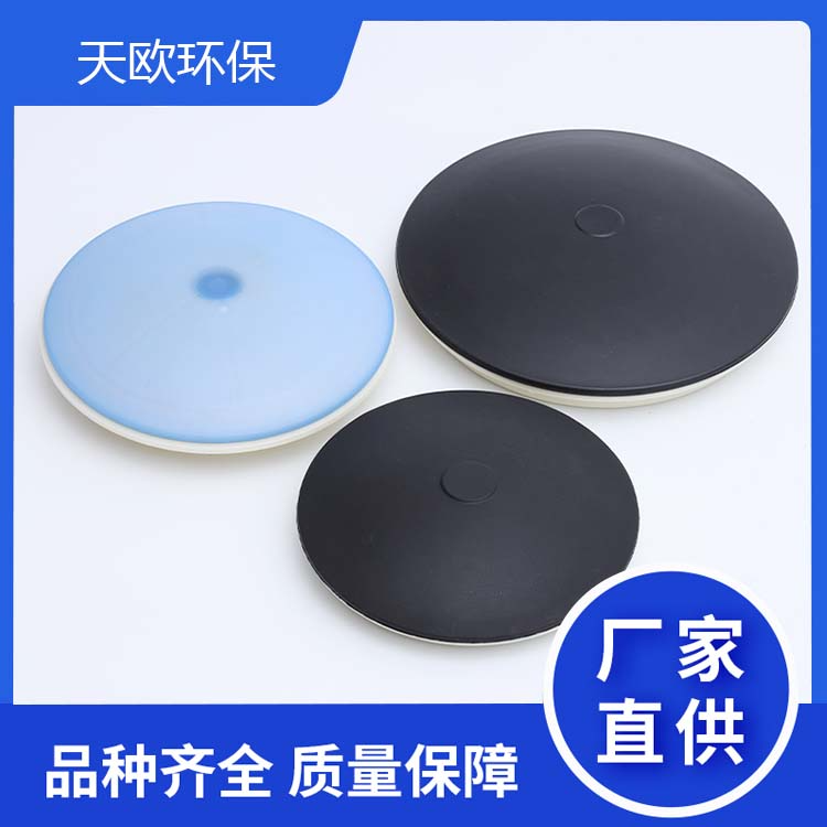
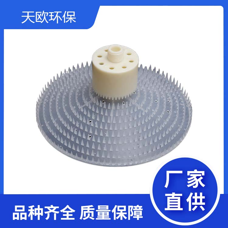
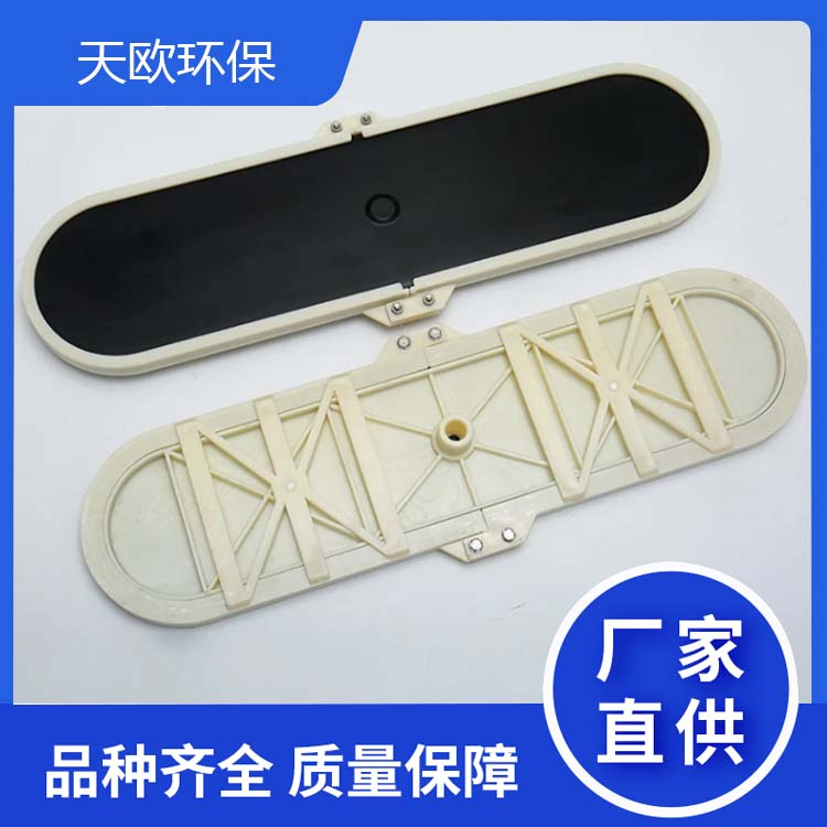
Bubble Diffuser Membrane: EPDM, Silica, Polyurethane
Bubbletubing Lining: ABS, UPVC, PP
Aerator Connector: 304 Stainless Steel
2. Specifications and Models
Serial Number | Model and Specification | Each setAerator diaphragm length |
1 | MKBQ-65*580 | 1160mm |
2 | MKBQ-65*1080 | 2160mm |
3 | MKBQ-65*1580 | 3160mm |
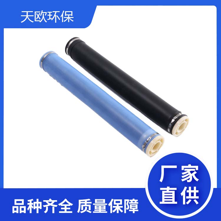
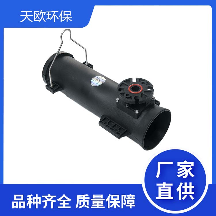
3. Product Overview
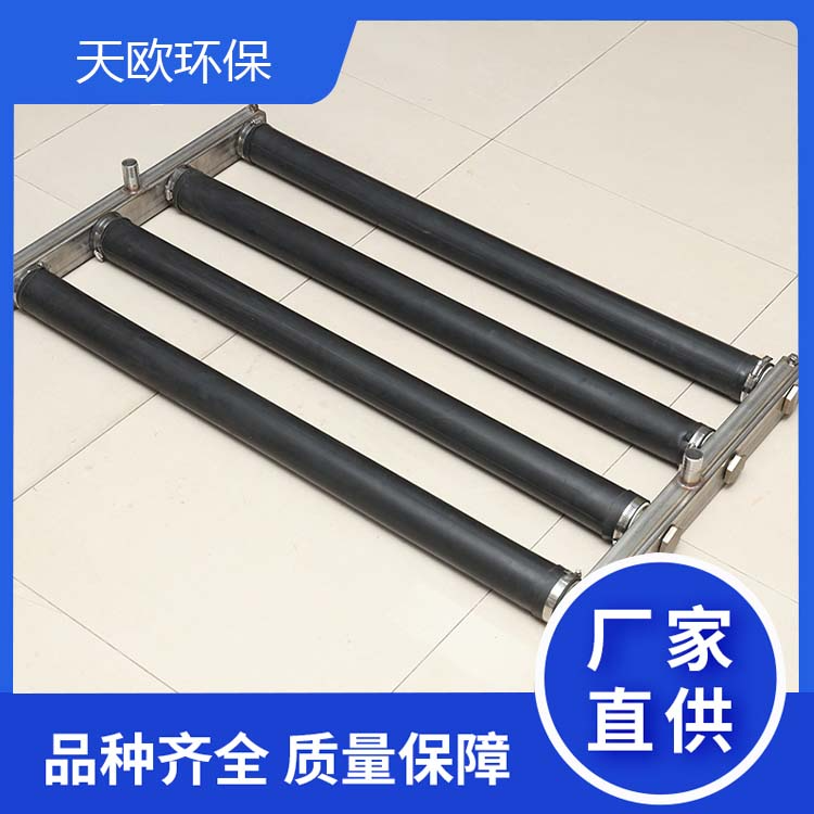
The MKBQ Upgradable Tubular Aerator is a new type of aerator developed by our company, integrating the advantages of similar foreign products. It allows for maintenance without interrupting water or gas supply. This product is suitable for new construction and renovation projects of various active sludge aeration basins in urban sewage and industrial wastewater treatment.
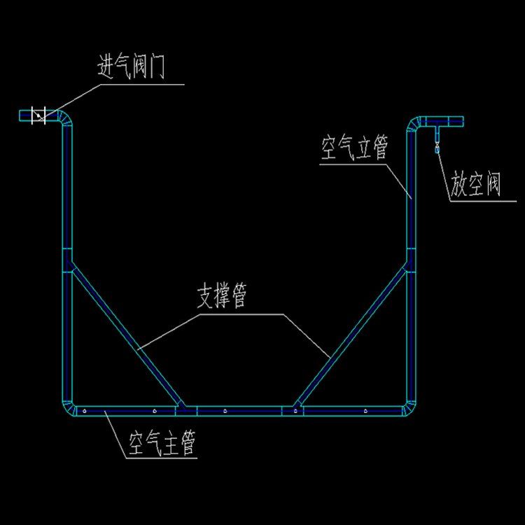
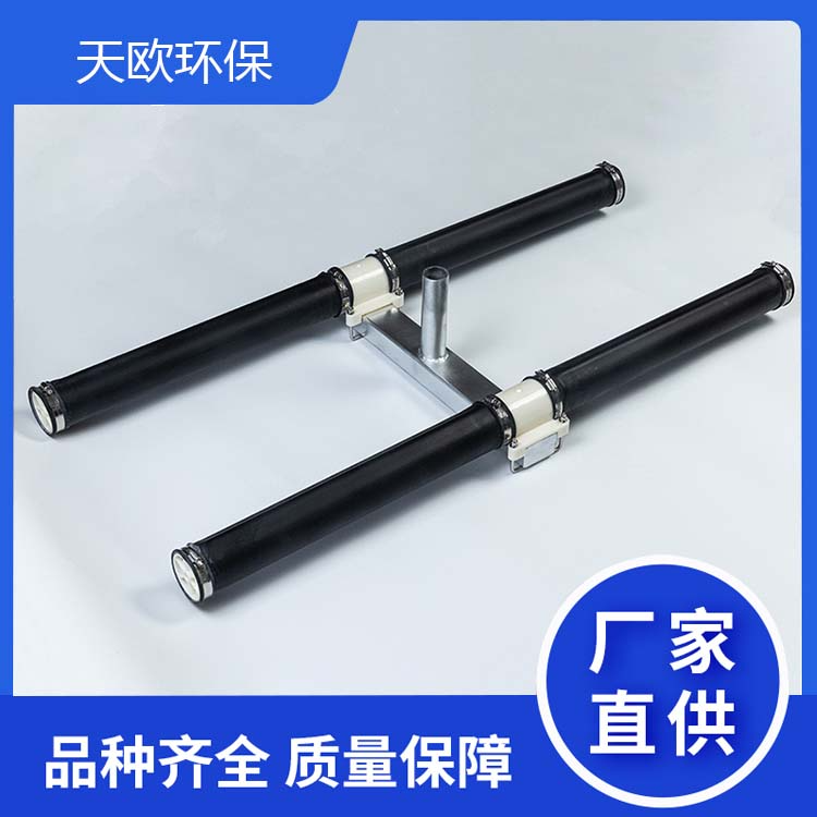
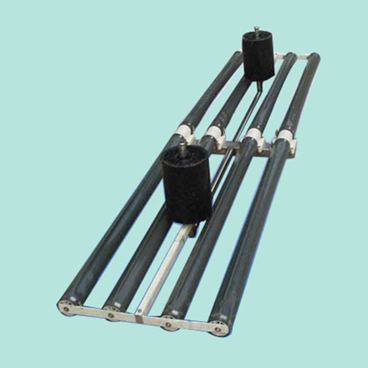
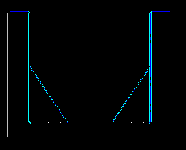
Each aeration system can determine the number of tube-type aeration devices based on the pool width, with a spacing of typically 500mm between devices. Each aeration system is an independent unit, equipped with an air intake and an exhaust valve. The frame of each system is in a "U" shape, and two thin tubes are diagonally pulled in the vertical section to ensure the stability of each system.
4. Product Advantages and Features
The MKBQ elevated tube aerator can directly remove each aeration system above the water surface for thorough cleaning and maintenance, keeping the aeration system in pristine condition. This reduces fan wear, maintains high power efficiency, and lowers operational costs.
Uniform aeration, fine bubbles, high oxygen utilization, and high power efficiency.
Good flow rate, stable flow, low resistance, and low energy consumption.
Rationally structured, easy to install, with 304 stainless steel rods for connection, long service life.
No air purification needed, no backwashing required, easier management.
Each aeration system can be controlled individually.
5. Product Technical Specifications
Serial Number | Specification Model | Each set | Airflow rate | Service Area |
1 | MKBQ65*580 | 1160mm | 4-8m³/set.h | 1-2 sq. m. per set |
2 | MKBQ-65*1080 | 2160mm | 8-14m³/set.h | 2-4sq. m/set |
3 | MKBQ-65*1580 | 3160mm | 12-20m³/set.h | 3-5sq. m./set |
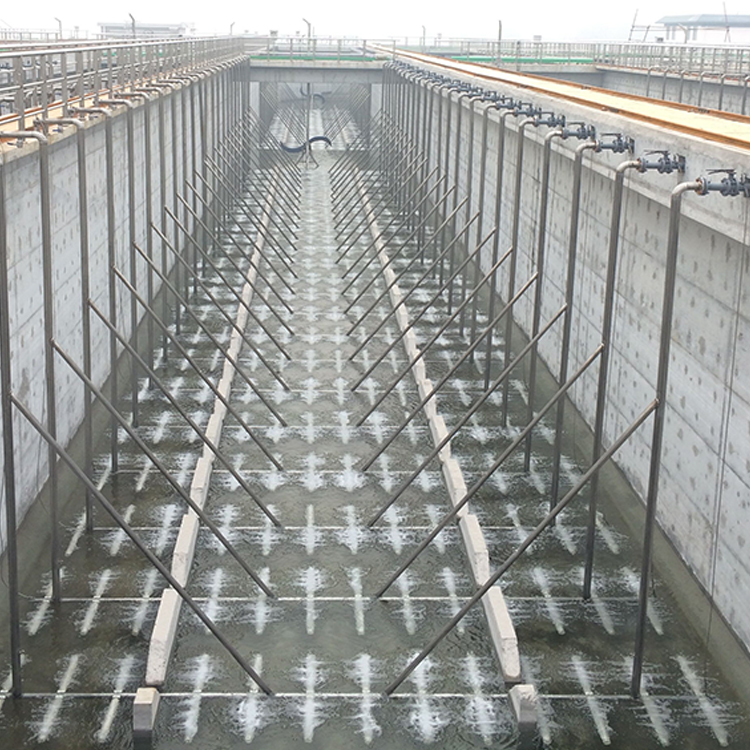
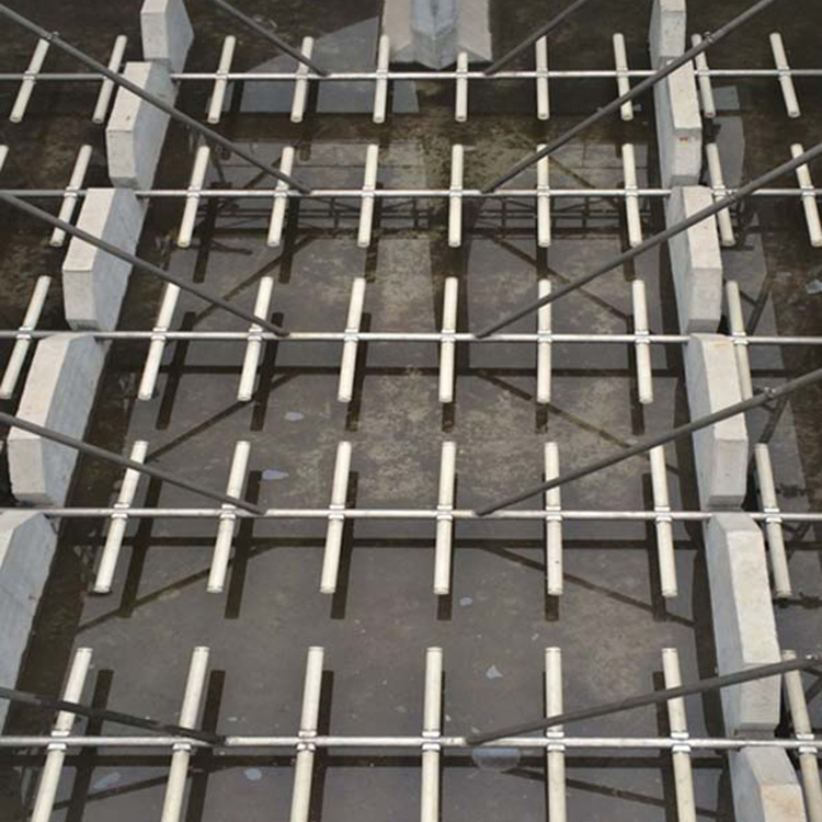
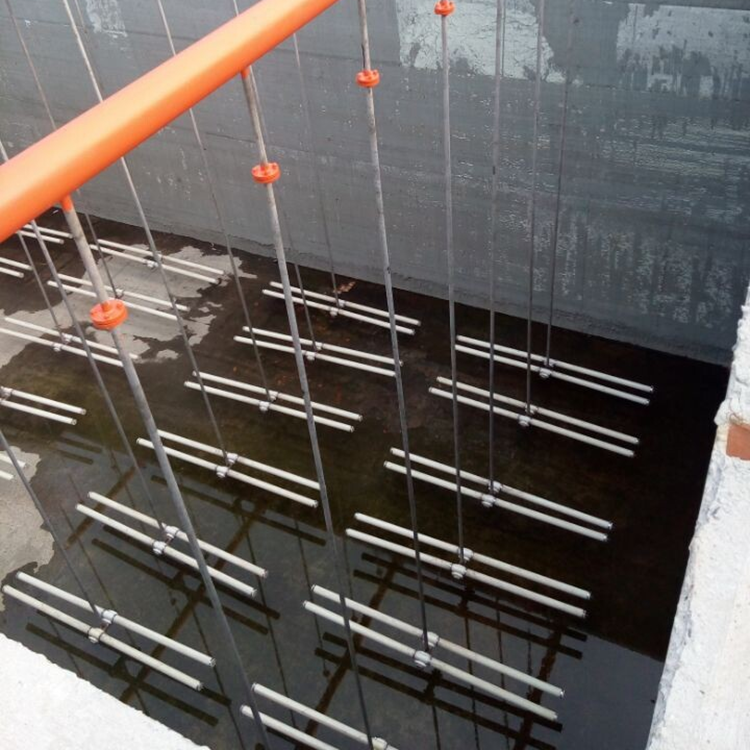
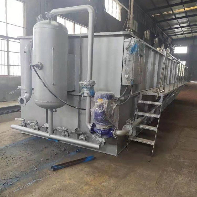
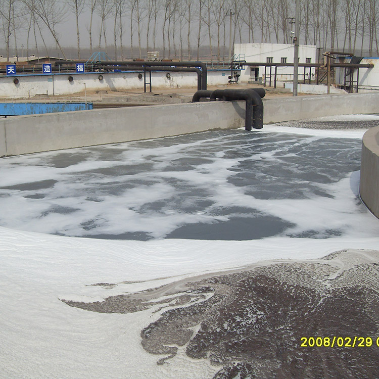
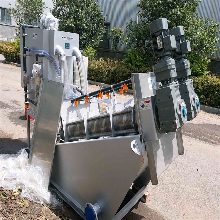
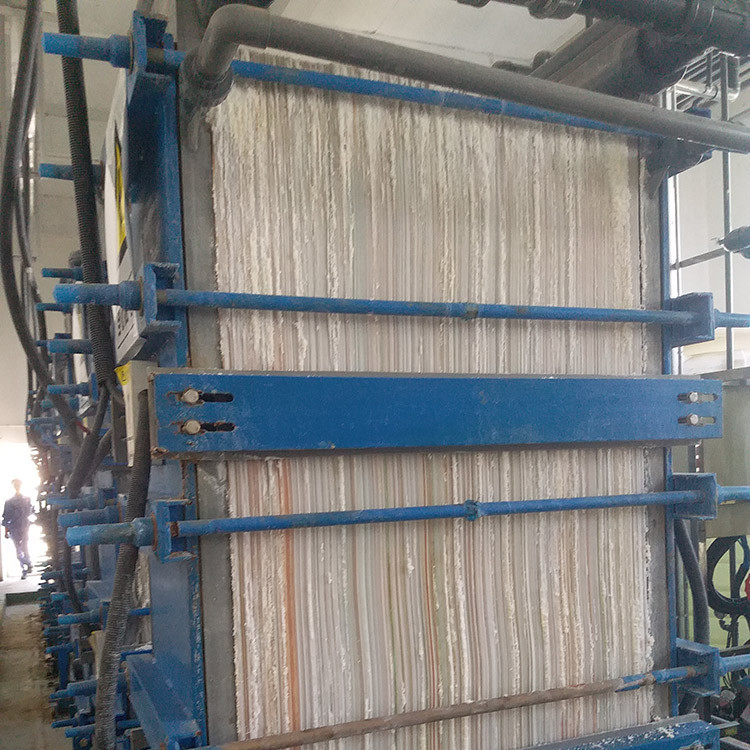
6. Engineering Site Photos
Installation Completed On-Site Photo

Test Run Site Photo

7. Installation Program Description
(1) The MKBQ aeration system can be generally evenly arranged at the bottom of the water treatment pond, with the aeration equipment positioned 100-250mm from the bottom, and the longitudinal spacing is typically around 500mm.
(II) Installation Parts and Accessories
Air Supervisor:
Weld the pipe according to the drawing dimensions into a single, continuous pipe.
Mark the entire pipeline, perform double-sided drilling, and weld elbows and other pipeline fittings.
The distance between pipe openings is generally around 500mm, with specific dimensions determined based on actual oxygen demand.
Ensure that both holes on the air main are aligned in a straight line during the drilling process, and that all holes on each side of the air main are in a single plane.
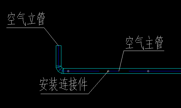
Air Straight Pipe
Cut the air upright pipe to size according to the drawings, then connect one end to the pipeline valve within the pipeline trench and the other end is fixed on the rim of the pool with a U-bolt; one upright pipe is fitted with an emptying valve.
In each aeration system group, a support pipe is welded between each vertical pipe and the main pipe, forming two triangular structures, further ensuring the stability of each aeration system group.

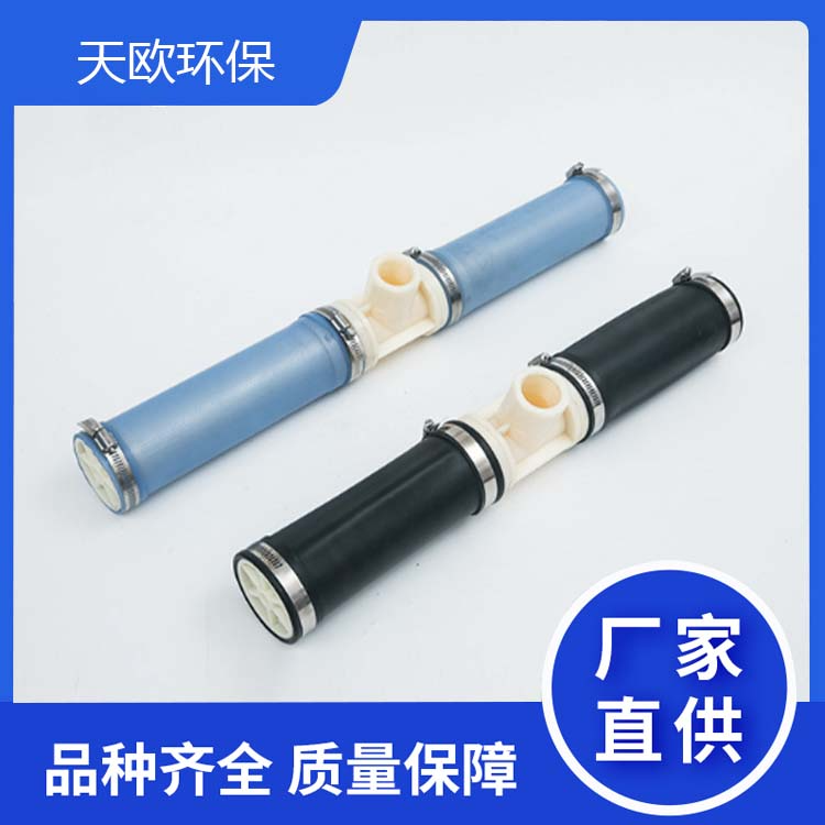
Aerator
The spacing between aeration devices is generally around 500mm, with specific dimensions determined by engineering requirements.
The aeration blowers are available in three lengths: 580, 1080, and 1580mm, and can be customized according to customer requirements. The membrane is packaged separately upon shipment to prevent wear during transit. When installing the membrane, please note that the unperforated part should be vertical to ensure the aeration holes blow horizontally. This prevents clogging of the membrane during shutdown. The clamps at both ends of the membrane must be tightened to avoid leakage and detachment.
Installation Process Diagram:
Air Main Welding and Positioning

Install air vertical pipes and support pipes
Install an aeration device
Adjust the aeration nozzle to ensure it is aligned in a straight line.
Inspect all weld points and screws for gaps to prevent leakage.
Installation completed, commissioning and acceptance.
Flat installation diagram

8. After-Sales Service & Maintenance
8.1 Common Faults of Elevator Aerator and Solutions
Serial Number | Fault Phenomenon | Fault Cause | Solution |
1 | EachAirManagerVarying aeration volumes | EachAirSupervisorGas supply volume varies | Adjust intake valve |
2 | Locally uneven aeration | Aerator Clog | 1 Clean with acid washing equipment. 2 Close or reduce othersGas Transmission MainThe gas supply volume, increase this lineSupervisorFlow rate until aeration is uniform. Remove the aerator for cleaning. |
3 | MetalConnectorsLeakage at location | Improper converter installation | Reinstall the converter |
4 | AerationApplianceLocally, there are large bubbles. | Diaphragm tear. | Replace the aeration diaphragm. |
5 | Both ends of the diaphragm have large air bubbles | Gasket flange loose | Tighten the diaphragm clamp or replace the clamp |
8.2 Procedures and steps for routine maintenance, testing, and replacement of parts:
8.2.1 Inspect the aeration pond daily and strictly follow the operational procedures. In case of uneven aeration and the presence of local large air bubbles, refer to the previous section of this maintenance manual for troubleshooting and fault elimination.
8.2.2 Step for Diaphragm Replacement:
Firstly, remove the aeration device.
Inspect the clamp for any damage.
Loosen the collar, remove the old diaphragm, and replace it with the new one.
When tightening the clamp, ensure the clamp ring is parallel to the air connection pipe.
8.3. Use and Other
The aeration device must be filled with water promptly after installation in the empty pond to prevent damage from sunlight exposure, electric welding sparks, or sharp objects falling into the pond.
This product is not suitable for heavy pressure, should not be stored outdoors, and must be kept away from fire sources and hard objects to prevent damage.
8.4 After-Sales Service Measures
One-year warranty, free repair during the warranty period (for products covered under warranty) starting from the date of completion and acceptance. Provide tracking service for the equipment supplied by the company.
The company will respond within 1 hour after receiving the customer's notification and arrive on-site within 48 hours Z night.