


Material
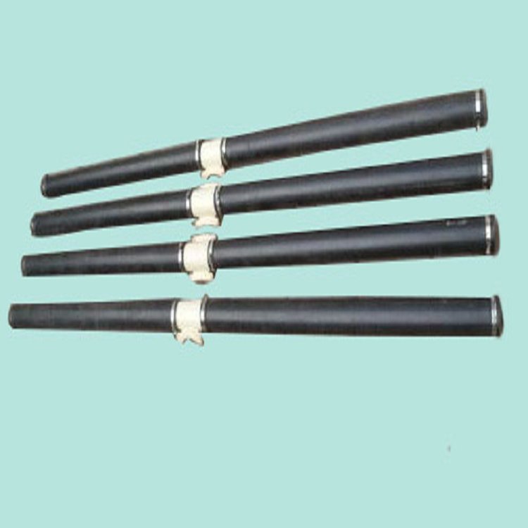
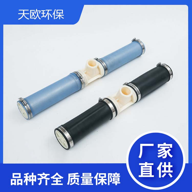
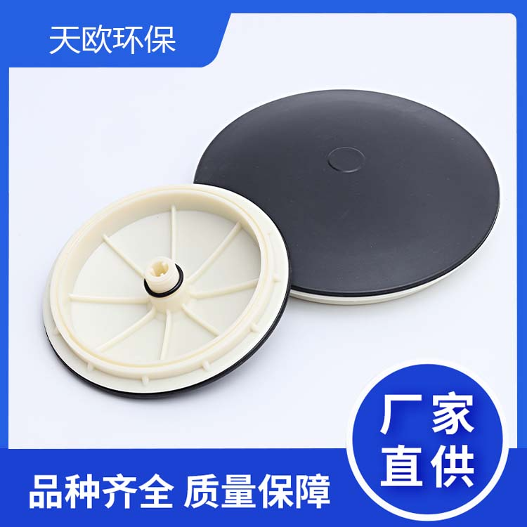
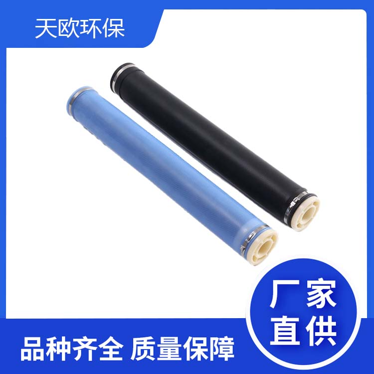
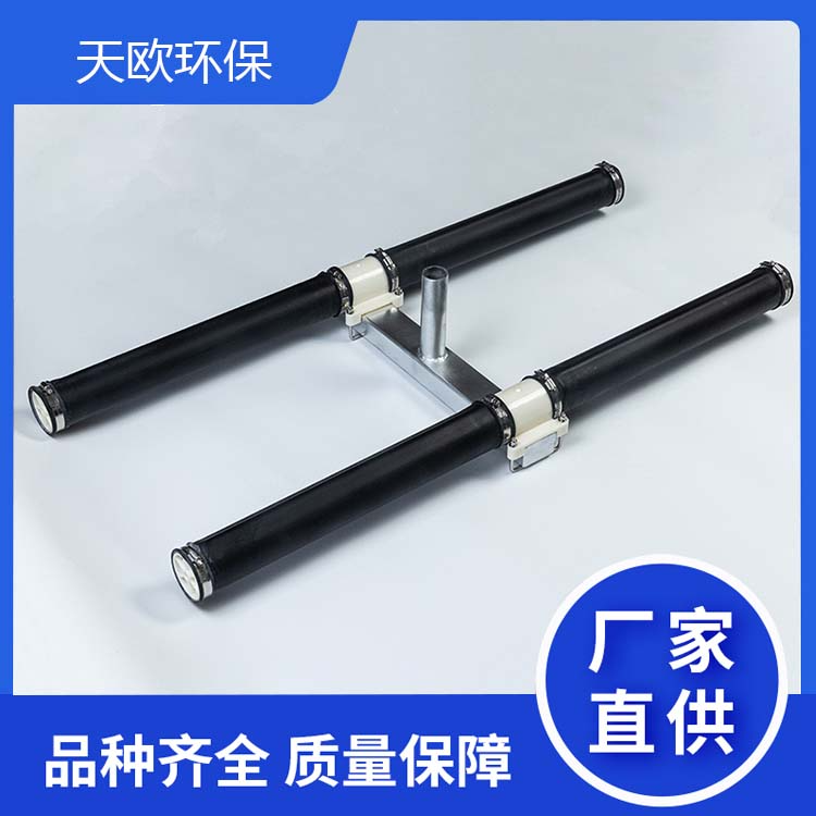
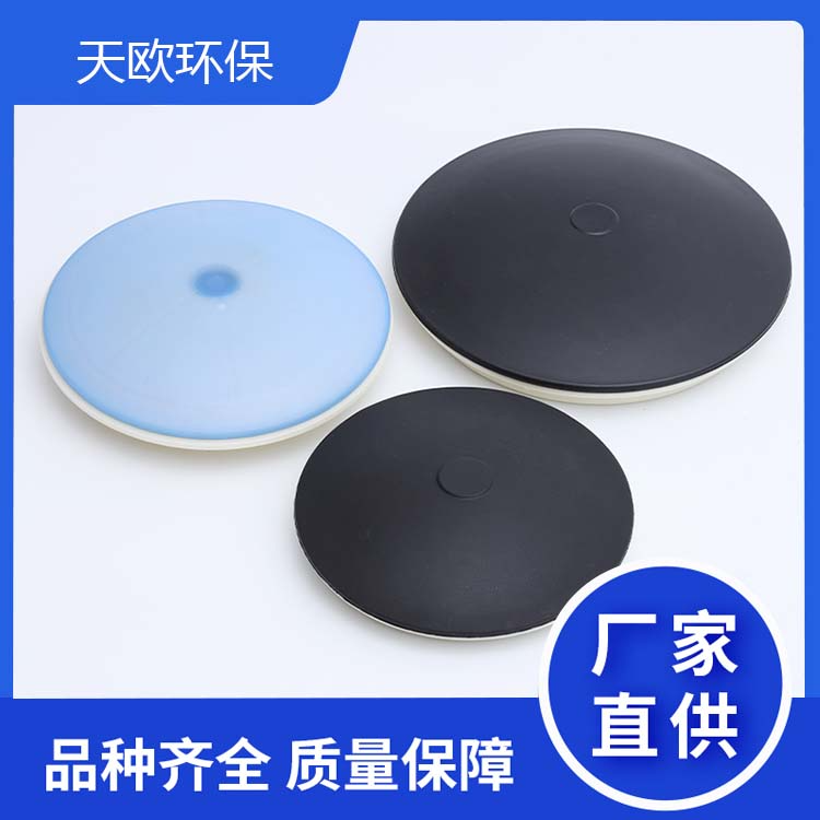
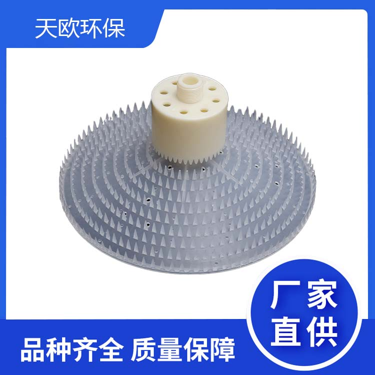
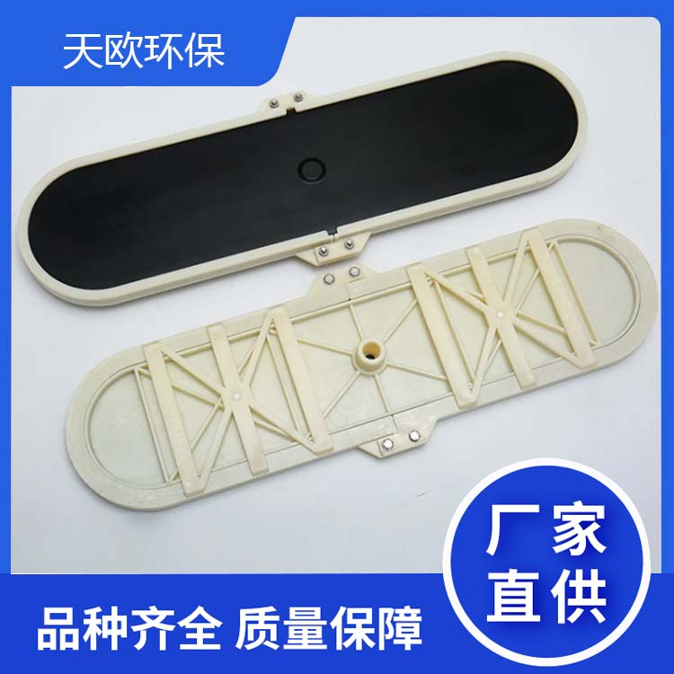
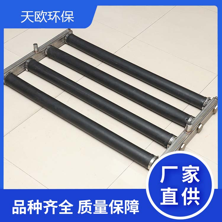
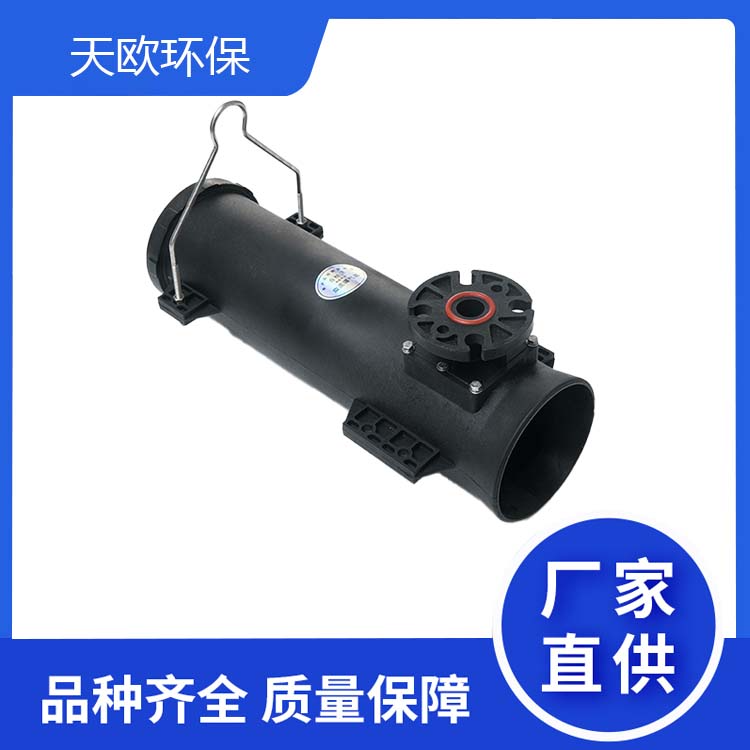
The eight-tube suspended aeration diffuser is composed of an inner lining tube, diaphragm, clip, gas chamber, and counterweight band. The aeration diaphragm is made of silicone rubber or EPDM material, the inner lining tube is available in UPVC or ABS, the clip band is made of 304 stainless steel, and the gas chamber is made of 304 material.
2. Specifications and Models
XG-1300-8
3. Product Overview
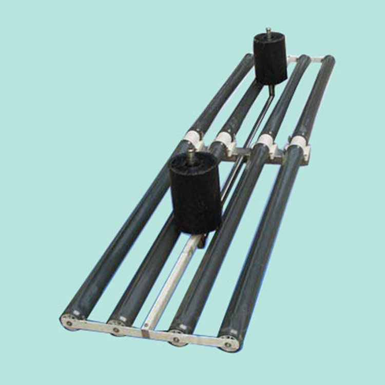
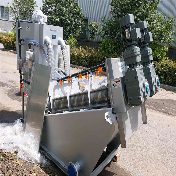
Our Suspended Chain Aerator is a new oxygenation aerator developed after years of effort, drawing on the advantages of various similar foreign products. It is the core equipment of today's wastewater treatment technology – the Improved A/O Process (Active Sludge Biochemical Process). It acts effectively on all parts of the pond, providing uniform aeration and low energy consumption.
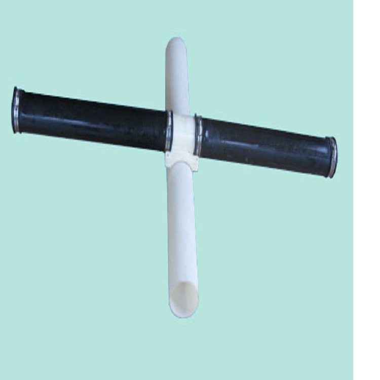
The Suspended Chain Aerator consists of three parts: the aerator, the suspended chain, and the water surface air supply pipe. The aerating diaphragm is made of silicone rubber or composite material, the suspended chain is a high-strength polyethylene tube, and the floating pipe is an anti-ultraviolet rigid-wall flexible plastic tube.
4. Product Advantages and Features
The composite diaphragm has a long lifespan, reaching 5-8 years, and completely solves the缺点 of the rubber diaphragm being prone to tearing and having a short service life.
High collision resistance, not easily damaged.
Ø Internally equipped with a non-return valve, it completely solves the problem of backwater.
The floating pipe is made of UV-resistant material and fully welded, which completely solves the issue of air leakage and boasts a long service life.
All components are made of corrosion-resistant materials.
5. Installation Program Overview
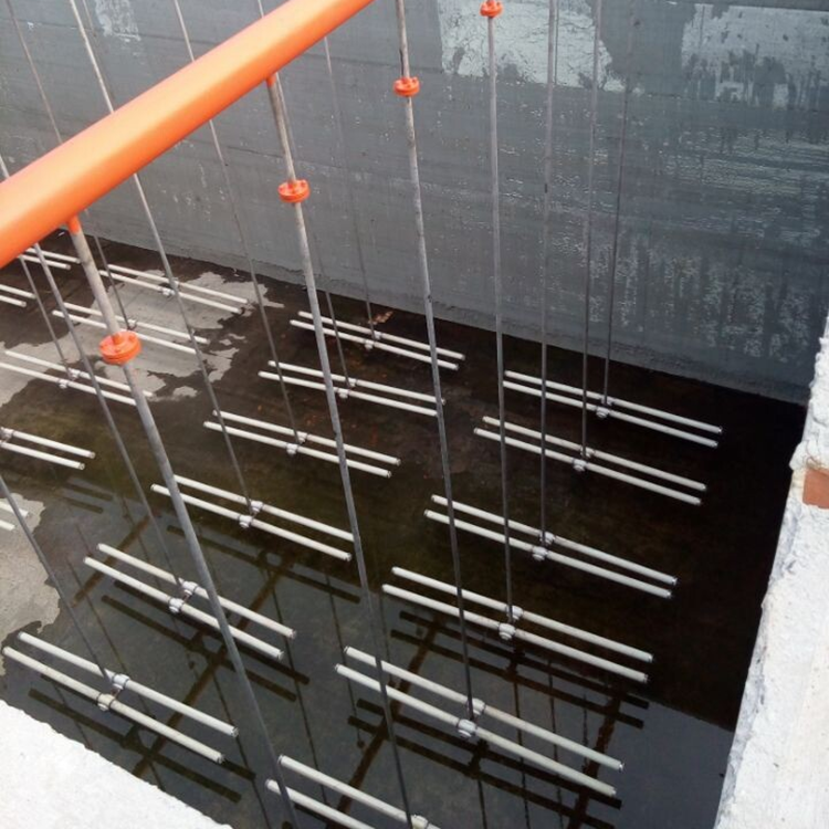
5.1 Suspended chain aeration diffusers are typically evenly arranged at the bottom of the water treatment pond, with a distance from the bottom of 100-250mm, and the longitudinal spacing is usually 300-1000mm.
5.2 Installation Parts and Accessories
Gas Transfer Hoses and Clamps
Gas Transmission Floating Pipe and Cap
Suspension Link Head and Clamp
Flexible Sling Pipe and Clamp
Aerator
5.3 Installation Method
At the bottom of the pool, sequentially number and arrange the gas delivery float pipes and caps in an orderly manner. Weld them into a single pipe using a plastic welding machine. Ensure that the suspended joint connections are aligned in a single parallel line.
Chains are cut to the design size. One end of the chain is connected to the aeration device with a clamp, and the other end is connected to the buoyancy tube.
Connect the gas conduit to the buoyancy pipe and secure it with a clamp.
Connect the wire rope to the float pipe.
Tighten the gas conduit connection to ensure no leakage.
Tie the wire rope with a soft rope to the embedded part at the pool edge. Begin filling the pool.
After the water is full, first turn on the fan to clean the pipeline. Connect the gas supply hose to the manifold. Adjust the length of the steel wire rope.
Turn on the blower and adjust the air intake valves to ensure even aeration across each chain.
Ø Note any leaks at all connections.
5.4 Installation Precautions
The clamp must fit into the groove of the joint.
Comprehensive blow cleaning of the air conduit is mandatory before the installation of the hose.
During installation and after installation, on-site activities involving open flames, such as welding, are strictly prohibited. If such work is necessary, cover the aeration unit with fire-resistant materials to prevent equipment from being damaged by heat.
The aeration blower must not be thrown or pulled during handling and installation to prevent wall abrasion.
After installation, all connection heads should be checked for compliance.