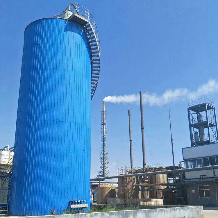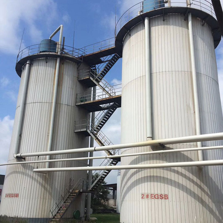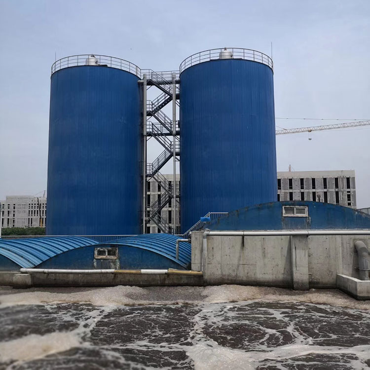


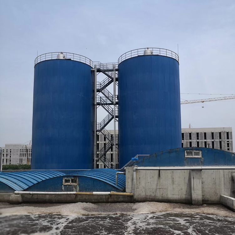

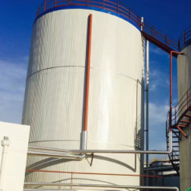
IC Anaerobic Reactor Introduction (also known as IC Anaerobic Tank or IC Anaerobic Tower):
The IC anaerobic reactor is a multi-stage internal circulation reactor, representing a type of third-generation anaerobic reactor (with UASB being the representative of the second-generation anaerobic reactor). Compared to the second-generation anaerobic reactor, it requires less space, has a higher organic load, stronger shock resistance, more stable performance, and simpler operation and management.
Wastewater enters the reaction chamber from the bottom of the IC reactor, where it is uniformly mixed with anaerobic granular sludge. Most of the organic matter in the water is converted into biogas here. The produced biogas is collected by a gas collection hood in the reaction chamber and rises along the riser pipe. As the biogas rises, the mixed liquid from the reaction chamber is lifted to the gas-liquid separator at the top of the reactor. The separated biogas is discharged through the biogas outlet pipe at the top of the separator. The separated sludge-water mixture returns to the bottom of the reaction chamber via the recirculation pipe, where it is thoroughly mixed with the granular sludge and incoming water, achieving an internal circulation of the mixed liquid in the reaction chamber. The name of the IC reactor comes from this internal circulation. The result of the internal circulation is that the reaction chamber not only has a high biomass and a long sludge age but also a high upflow velocity, which completely fluidizes the granular sludge within, resulting in a high mass transfer rate and thus enhancing the biochemical reaction rate, significantly improving the reaction chamber's ability to remove organic matter.

Wastewater processed through the first reaction chamber automatically flows into the second chamber for further treatment. The remaining organic matter in the wastewater can be further degraded by anaerobic granular sludge in the second chamber, resulting in better purification of the wastewater and an improved effluent quality. The produced biogas is collected by the gas collection hood in the second chamber and then enters the gas-liquid separator through the gas collection pipe. The sludge-water mixture from the second chamber is then transferred to the sedimentation zone for solid-liquid separation. The treated supernatant is discharged through the outlet pipe, while the sedimented sludge can be automatically returned to the second chamber. This completes the entire treatment process of the wastewater within the IC reactor.
Reactor Structure:
The IC reactor is essentially composed of two stacked UASB reactors in series. The biogas produced by the lower UASB reactor serves as an internal driving force, creating a density difference between the upflow and recycle pipes, thereby enabling the internal circulation of the lower mixed liquid and achieving enhanced preliminary treatment of the wastewater. The upper two UASB reactors continue the post-treatment (or refined treatment) of the wastewater, ensuring the effluent meets the expected treatment requirements.
IC Reactor Working Principle: It is similar to a series of two UASB reactors. Functionally, the reactor is divided into five sections from bottom to top: Mixing Zone, Anaerobic Zone 1, Anaerobic Zone 2, Sedimentation Zone, and Gas-Liquid Separation Zone. The basic structure of the IC Reactor is as shown in the figure (request).
IC Anaerobic Reactor Process Features
IC utilizes a two-stage UASB series for anaerobic treatment with分级, which reduces the effluent VFA concentration, extends the biological retention time, and ensures stable reaction performance.
Our unit employs an ultra-rotary water distribution system, which allows for thorough contact and mixing of wastewater, internal recycled water, and granular sludge. This results in more even water distribution, no dead corners, no clogging, high treatment efficiency, stable operation, and good effluent water quality.
(2) The mixing of the ultra-rotating flow water distribution method maintains a high upward flow velocity within the IC, allowing the biogas produced in the anaerobic sludge to be rapidly released, preventing it from remaining in the granular sludge. This relatively stable operating environment enables the sludge to grow rapidly and uniformly, ensuring the effluent quality of the anaerobic reactor.
(3) Based on extensive engineering experience, Guangbo Environmental Protection Co., Ltd. has optimized and improved the three-phase separator structure, making it highly robust and long-lasting.
(4) The optimized and improved three-phase separator gas chamber is equipped with a slag挡板 at the inlet, which prevents mud from escaping.
IC Anaerobic Reactor Main Components:
Water Distributor: Utilizes an ultra-rotary flow water distribution system, allowing for thorough contact and mixing of wastewater, internal recycled water, and granular sludge. This ensures uniform distribution, no dead zones, no clogging, high treatment efficiency, stable operation, and excellent effluent water quality.
Three-phase Separator: Based on hundreds of engineering experience, our company has optimized and improved the structure of the three-phase separator, resulting in high strength and extended service life. The optimized separator features a slag-boarding at the gas chamber inlet, which prevents mud from escaping.
Carbon Dioxide Separator: Removes liquid water from the biogas through principles such as deceleration, centrifugal force, collision, directional change, and coalescence, achieving purification. The wastewater is then returned to the distributor through pipes.