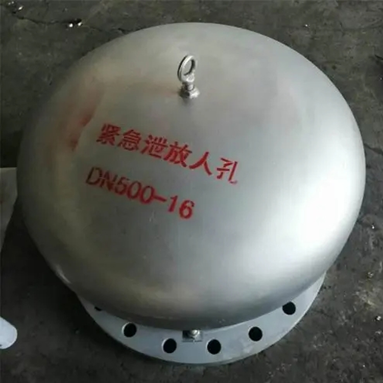


Manholes are safety emergency venting devices installed on the top of storage tanks, commonly used with fire extinguishers and mechanical breathing valves. They not only prevent accidents caused by sudden overpressure or vacuum inside the tank due to unexpected reasons, but also serve as a fire-retarding barrier, ensuring the safety of the tank. Particularly suitable for arch-shaped atmospheric tanks sealed with nitrogen, they offer features such as pressure-regulated discharge and intake, flexible operation, fire-retarding safety, compact structure, good sealing performance, and reliability.
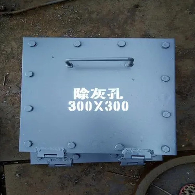
Manholes are categorized into emergency relief manholes, explosion-proof flame-retardant breathing manholes, tank-top manholes, tank-wall manholes, and core manholes, among others.
Housings are typically made from 304, 316L stainless steel plates or carbon steel.
Structure
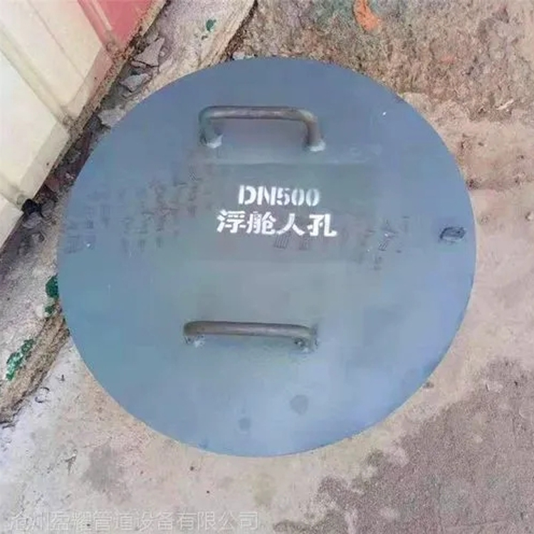
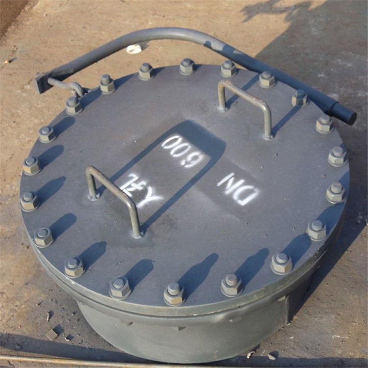
There are prefabricated manholes available, typically with a diameter of 600mm. The center of the manhole is usually 750mm from the floor, facilitating staff access to and from the oil tank or ventilation during installation, cleaning, and maintenance.
The manhole of non-metallic oil tanks is located on the top of the tank, while the manhole of metallic oil tanks is situated on the lower ring plate of the tank wall. Most are circular holes with a diameter of 600mm, with the center 750mm from the bottom plate. These are used for personnel to enter and exit the tank for cleaning or maintenance purposes and are also known as hatch doors. During tank inspection and cleaning, the manhole is used for lighting and ventilation. For vertical tanks with a capacity of 5000m3 or less, 1 to 2 manholes are provided; for those above 5000m3, 2 manholes are installed. The installation of the manhole should be no more than 90° from the inlets and outlets of the pipeline. When only one manhole is provided, it should be placed opposite the tank's light hole at the top; when two manholes are installed, one should be opposite the light hole, and the other should be at least 90° from the first.
The manhole should be located near the right side of the oil pipeline entry and exit, and as close as possible to the sealed door of the tank room, for personnel to enter and exit, maintain the oil tank, and connect the ventilation.
Due to the manhole being installed on the lower cylindrical section of the oil tank, preventing leakage is particularly crucial. It is required that the two flange mating surfaces must ensure their flatness and free from any twisting. The reinforcing plates and flanges should be cut from a single steel plate as much as possible without being joined together. Sealing rings are machined on the flanges and lids, and special attention must be given to their protection during construction. Use 3mm thick asbestos rubber gaskets for sealing, and cracks are not permitted. When tightening the bolts on the manhole cover, apply force diagonally and evenly in pairs to prevent deformation of the cover.
1. Divided by the capacity of communication block, the pipeline cross-section blocks or the number of single-hole pipe holes with an inner diameter of 90mm, which correspond to pipe sections that can accommodate manholes with a width of 360mm and a height of 250mm (standard six-hole pipe blocks with an inner diameter of 90mm, abbreviated as standard blocks), are categorized into large, medium, and small sizes.
The size of the manholes set for communication pipelines should be based on the long-term capacity of the pipelines, not just the current construction capacity.
2. Divided by the direction of the manhole access
The manholes are categorized based on the direction of access, including straight-through manholes, three-way manholes, four-way manholes, and diagonal manholes. Detailed information is provided in Table 1. The diagonal manholes are further divided into five types: 15°, 30°, 45°, 60°, and 75°. Each diagonal manhole angle is suitable for a ±7.5° range.
3. Divided by the load-bearing capacity of the manhole cover
The manholes can be divided into two categories based on the load-bearing capacity of the cover: Steam-20 level and Steam-10 level.