


Designed according to the principle of torque balance. Within the specified load displacement range, the load torque and spring torque are always in balance. Therefore, when the pipeline and equipment supported by a constant-hoisting are displaced, a constant supporting force is obtained, without imparting additional stress to the pipeline and equipment. The constant-hoisting is generally used in situations where displacement stress needs to be reduced, such as in the boiler body of power plants, the steam, water, and flue gas ducts as well as burners in power stations, and in petrochemical equipment and other places where displacement stress needs to be reduced.
Usage and Application Range:
This standard applies to variable spring suspension brackets with a displacement range of VS (0~180mm), TD (0~120mm), a load range of 154~217,384N, and a service temperature range of -20℃ to 200℃.
Method of Representation
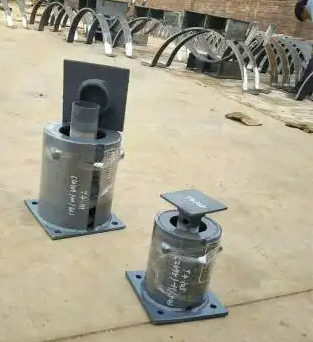
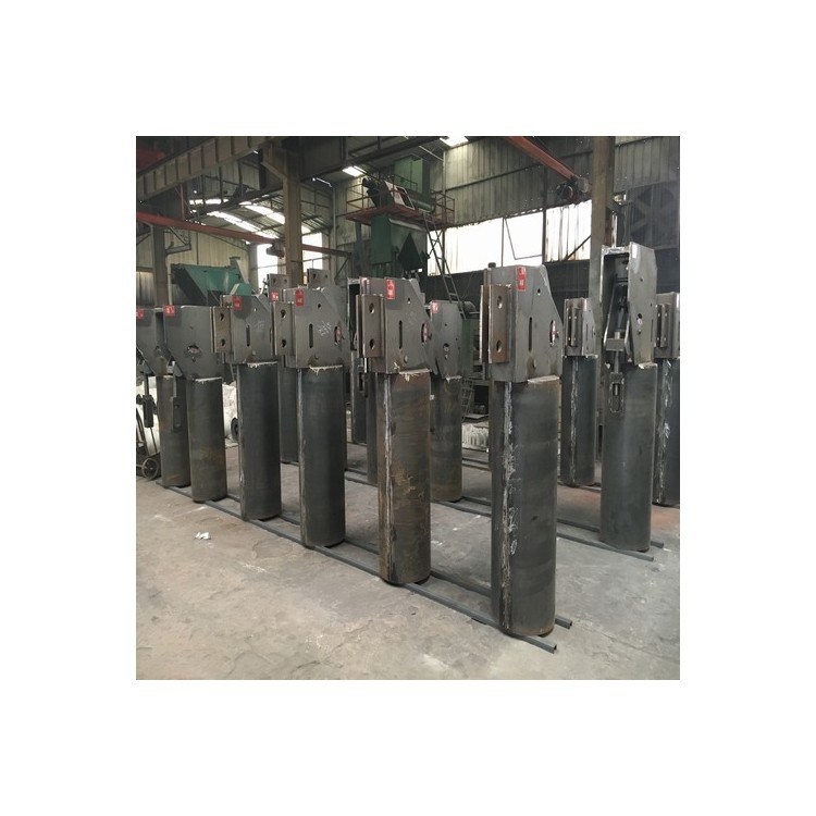
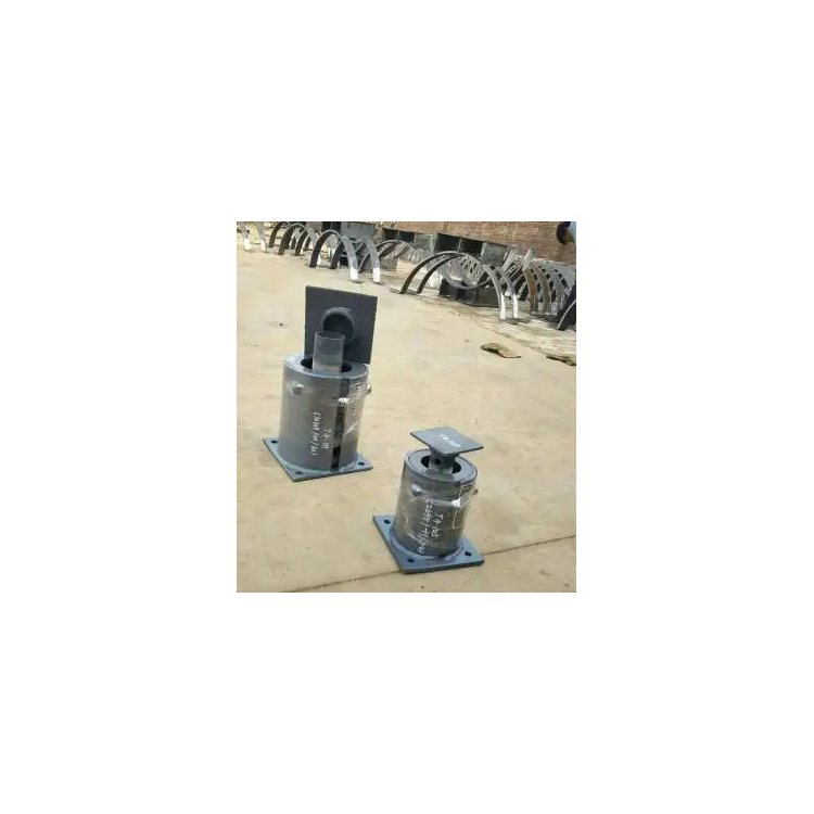
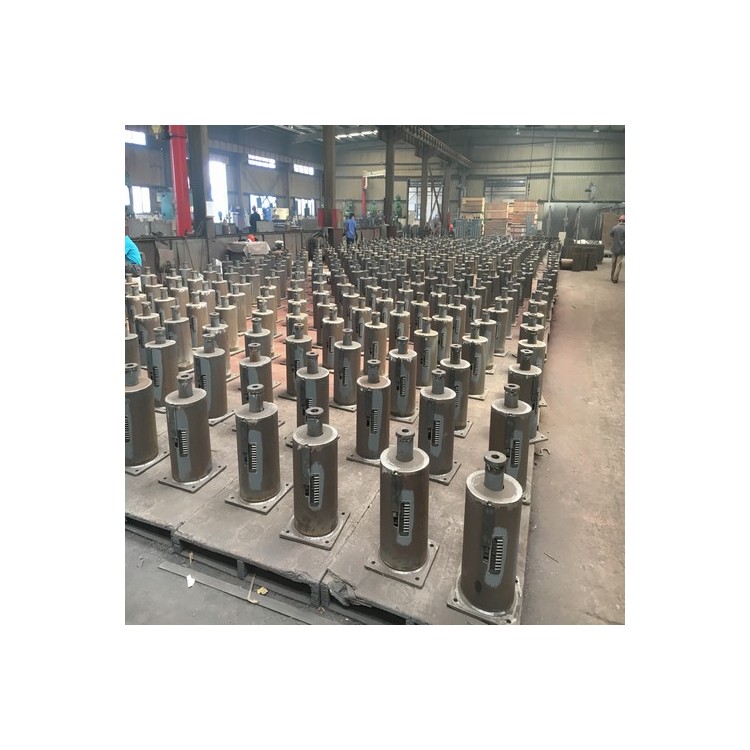
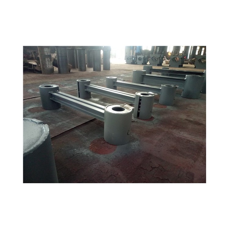
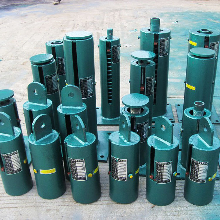
The adjustable spring suspension is mainly composed of cylindrical helical springs, displacement indicator plates, housing, and tension nuts, etc.
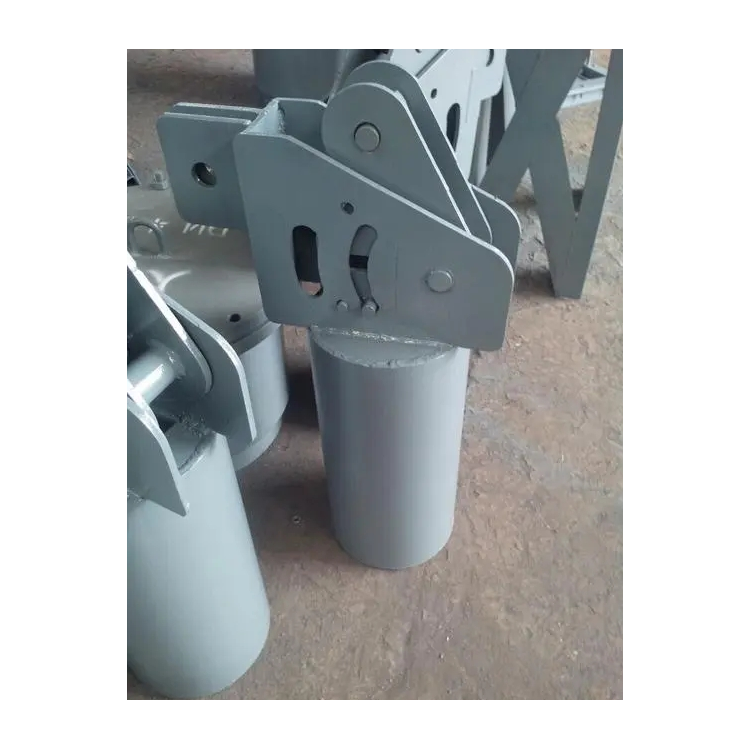
Variable spring suspension brackets are divided into seven types: A, B, C, D, E, F, and G, differing by their installation methods.
Type A --- Threaded Suspended Type
B Type —— Single Earring Suspended Style
C-type - Double-ear suspended type
D Type -- Upper Adjustable Shelf Type
E Type - Lower Adjustment Shelves
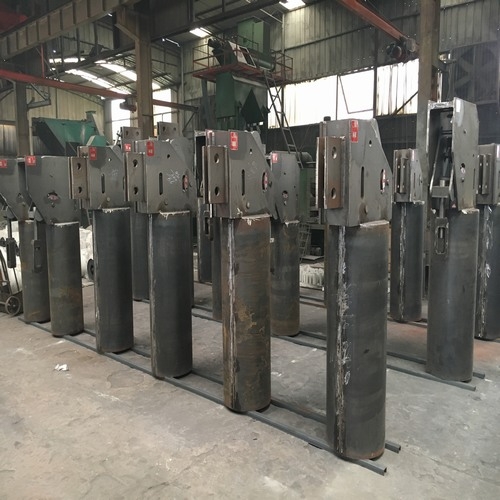
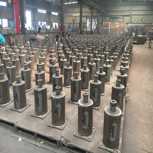
F-type ---- Support Bracket Type
G Type - Parallel Suspended Type
Installation and Usage:
Installation:
Type A
One end of the suspension rod is connected to the root; the other end is threaded into the top plate bolt hole of the spring support bracket and secured with a nut. The bottom of the basket nut is threaded onto the top end of the pipe suspension rod. Rotate the basket nut to lift the pipe to the designated installation position, then tighten with a nut.
2. B, C Type
The upper end of the spring suspension bracket is connected to the lifting rod or lifting plate, with the other end of the lifting rod or lifting plate anchored to the steel beam or floor. The rest is the same as the A-type.
3. D-Type
Secure the spring suspension bracket to the steel beam or floor with bolts, thread the lifting rod through the bracket body to connect with the pipe, rotate the top nut to hoist the pipe to the designated installation position, and then tighten the nut.
4. Type E
Secure the spring hanger with bolts to the steel beam or floor joists. The others are identical to Type A.
F-Type
Secure the spring support base plate to the foundation, steel beam, or floor with bolts, and support the bottom of horizontal pipes or bends at the top. When the actual support height on site differs from the designed installation height, adjust by turning the load column. The adjustment range is between Lmax and Lmin. The spring models VS30F0-9 are ±6mm, VS30F10-24 are ±12.5mm, and the spring models VS60F, VS90F, VS120F, VS150F, VS180F are ±25mm.
6. G Type
Turn the basket nut to tighten the hanger mounted on the steel beam or floor, adjust the hanger bracket to the designed installation height, and then secure the basket nut with the nut.