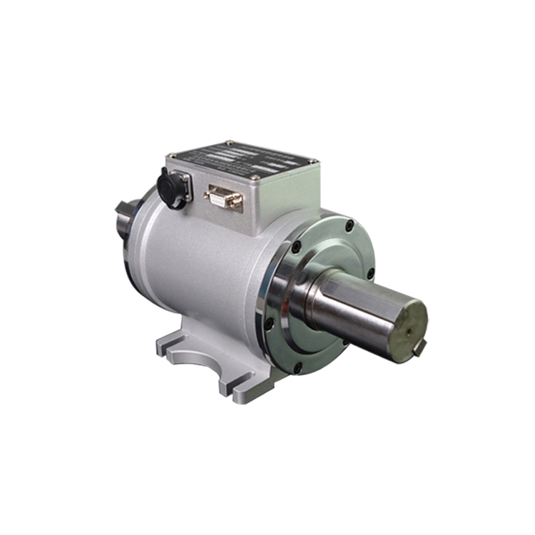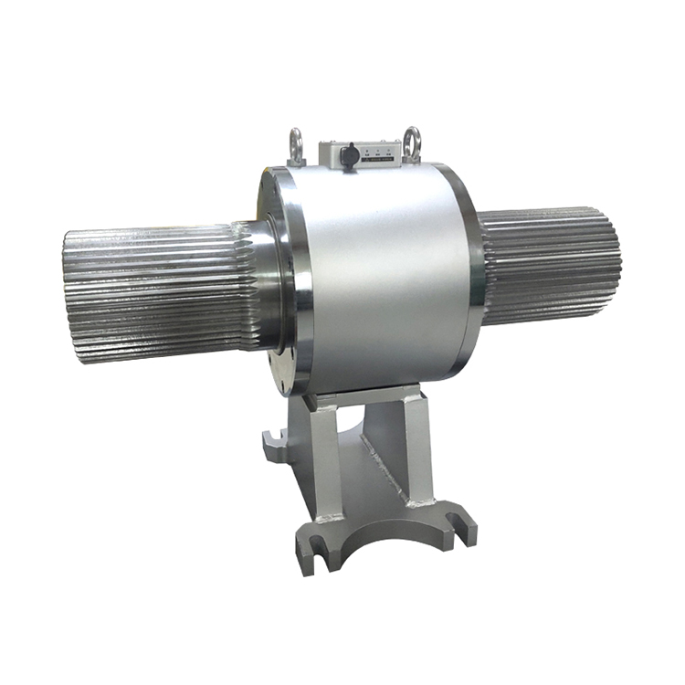
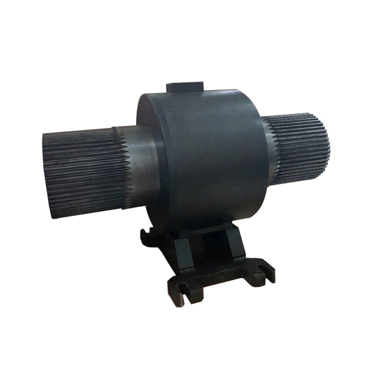


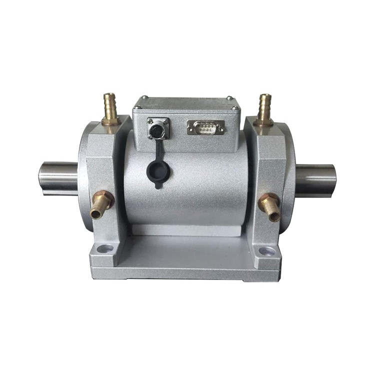

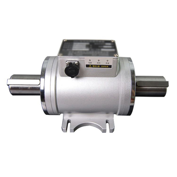
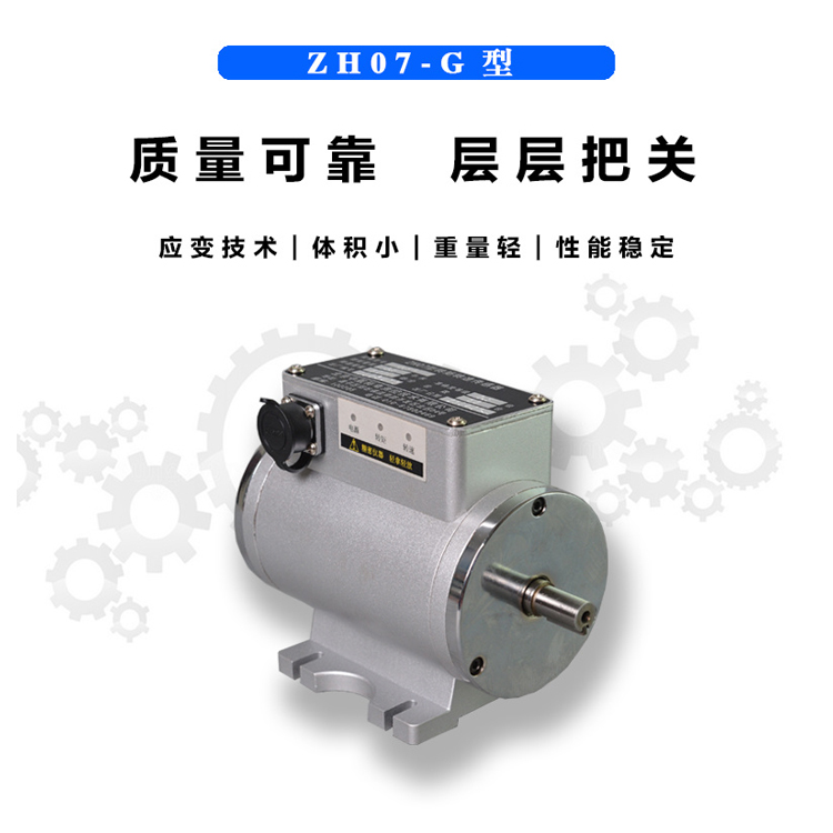
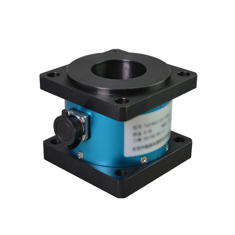

100KNm High-Range Double Helix Custom Torque Sensor Technical Specifications
Sensor power supply voltage: ±12C (optional 24VDC)
Torque Accuracy: 0.2% F.S., 0.3% F.S., 0.5% F.S.
Repetition: 0.2% F.S., 0.3% F.S., 0.5% F.S.
Linearity: 0.2% F.S., 0.3% F.S., 0.5% F.S.
0.2% F.S., 0.3% F.S., 0.5% F.S.
Overload Capacity: ≤150%
Insulation Resistance: >200 MΩ
Operating Temperature Range: -20°C to +60°C
Relative Humidity: <90%RH
Sensor power consumption: <4W
Load Current < 15mA
Damping meter dynamic strain wave response time: 3.2×10⁻⁶
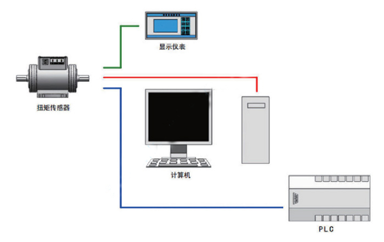
Sensor signal output is adjusted and can be directly fed into the PLC for collection.
100KNm High Range Double Helical Key Custom Torque Sensor Output Signal
Torque Standard Output Signal: Frequency Signal Output (Amplitude 5V)
Frequency Signal Output: 5KHz to 15KHz, zero point at 10KHz
Zero-torque frequency output: 10KHz
Positive torque full-scale frequency output: 15 kHz
Reverse torque full-scale frequency output: 5 KHz
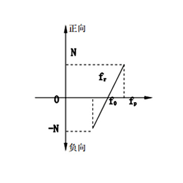
Torque Calculation Formula
Mp=N(f-f0)/(fp-f0)
Mr=N(f0-f)/(fr-f0)
MpPositive Torque; MrReversed Torque
N:转矩满量程; f0Torque Zero Output Frequency Value (KHz)
fpFull-scale Output Frequency Value (KHz)rReverse Full-Scale Output Frequency Value (KHz)
Real-time Torque Output Frequency Value (KHz)
Standard rotational speed output signal: Frequency signal output (amplitude 5V)
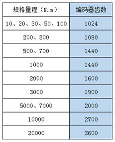
Speed measurement is achieved through encoder and photoelectric tooth disk methods, with the photoelectric tooth disk method used for high-speed measurements and the rotating encoder for low-speed measurements; it can also measure rotation angles. The number of pulses depends on the tooth count of the sensor's speed disk or the encoder's grating, with the output pulse count per revolution ranging from 60 to 3600 pulses/rev (available in A, B phases with a phase difference of 90°).
RPM Calculation Formula
n=60f/Z
RPM: Revolution Per Minute
f: Measured Rotational Speed Output Frequency (KHz)
Sensor speed disk gear teeth
100KNm High Range Double Helix Custom Torque Sensor with Other Signal Options
The sensor output signal amplitude can be increased to 24V (NPN, PNP options available)
Convert the frequency signal output from the sensor to F/V, F/I (optional analog voltage, current)
Serial Bus Method: Optional RS232/485
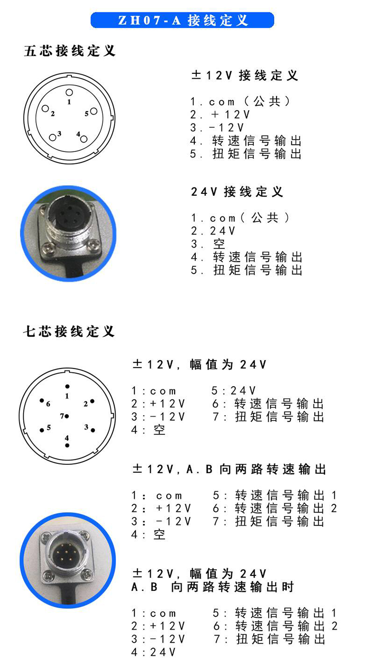
100KNm Wide Range Double Helix Custom Torque Sensor Wiring Definition
100KNm High Range Double Helical Key Custom Torque Sensor Reading Method
100KNm Wide Range Double Helical Gear Torque Sensor, Product Features
Utilize the principles of elastic strain measurement technology
Sensor signal output is available in various modes (frequency, analog, bus).
Signal and power are transmitted non-contact, without slip rings or brushes.
No zeroing or reversing required for measuring clockwise and counterclockwise torques
The signal employs frequency output mode, featuring high signal-to-noise ratio and excellent anti-interference performance.
Quick response, measurable starting torque, and transition process torque measurement available.
Unrestricted by rotational speed, capable of measuring real-time torque and power
Sensor linearity, good repeatability, high reliability, and strong anti-interference ability
Sensor structure is compact and widely used in various online testing and industrial control systems.
100KNm High Range Double Helix Custom Torque Sensor Mounting Method
Can be installed horizontally or vertically.
When installed horizontally, rigid or flexible couplings can be used; the couplings should be tightly mounted against the shaft shoulders at both ends of the sensor.
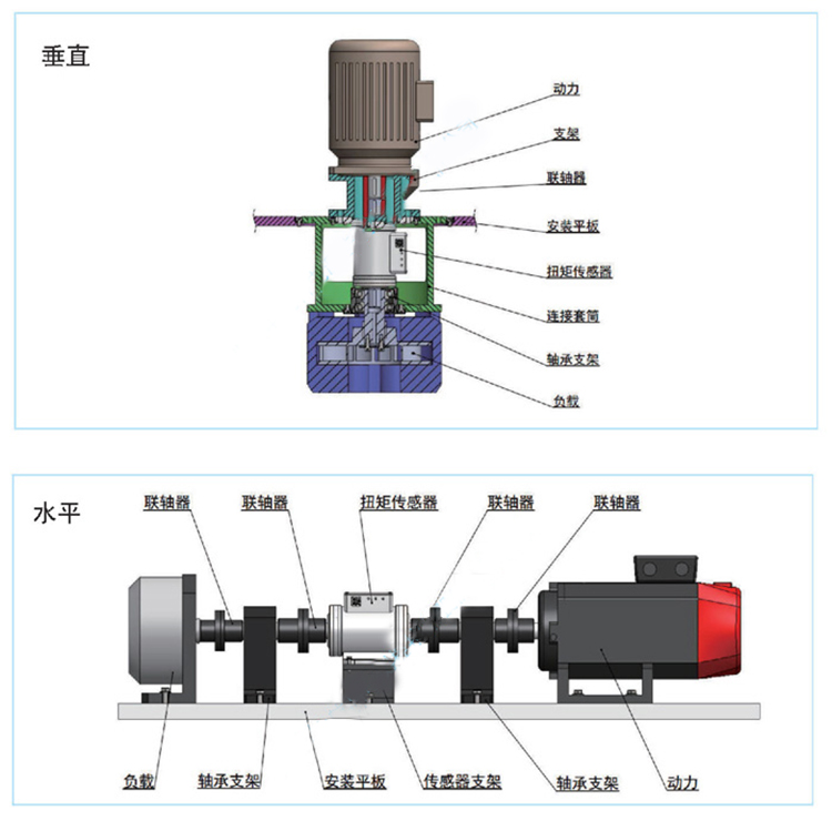
Torque sensor installation method
Sensor Installation and Usage Precautions
No live installation allowed; please disconnect the power during installation.
Do not directly strike or collide the sensor's output shafts with excessive force during installation.
When the horizontal installation shaft of the sensor is heavier, a bearing bracket should be added at the coupling location to prevent the sensor from bearing bending moments.
In cases of significant vibration or concentricity exceeding 0.05mm, use a flexible coupling first, and ensure the base is securely fastened to the pedestal.
In situations where installation conditions are favorable and high measurement accuracy is required, rigid couplings should be selected, and the base must be securely fastened to the foundation.
The base surface should be installed with sufficient strength to ensure stability and prevent excessive vibration.
This sensor is not waterproof or explosion-proof. Please note when using: (Customization available for special requirements).
Ensure proper grounding in the sensor system and implement shielding and isolation for signals that may interfere with each other.