


I. Product Overview
Adjusting the dampers is one of the important equipment in the flue and air duct systems of a thermal power plant boiler unit. It is used to regulate the flow rate of media in the flue and air duct systems, achieving the purpose of adjusting flow rates through different opening positions within the 90° rotation range of the damper. It serves in adjusting the primary and secondary air ratios in the boiler flue and air systems and the hot air temperature of the coal mill. Generally located in the cold and hot air ducts before the coal mill inlet, it can also be used to regulate flue gas flow rates in ducts containing ash particles, such as in the secondary smoke gas pipeline, etc.
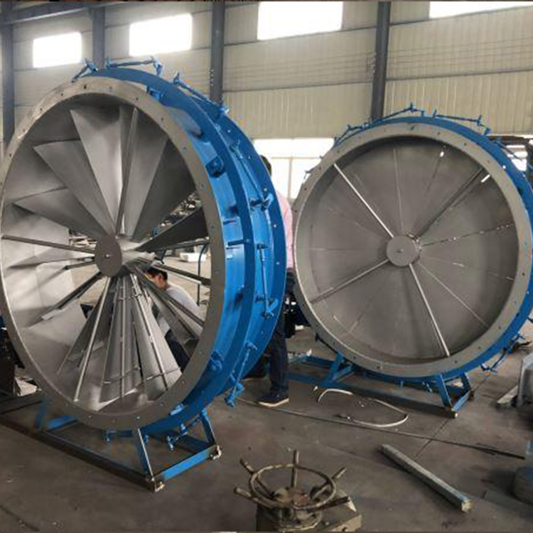
Louver-style adjustable damper door, suitable for cold and hot air ducts. As the damper varies in opening within a 90℃ travel, the flow rate and head of the working substance in the pipeline also change linearly accordingly. The linear adjustment characteristics of the door are excellent, and its operation is stable.
II. Performance Features
Adjust the air gate blade within the 90° angle travel range, with the full travel opening and closing time typically ≤50S (also available for selection according to customer requirements).
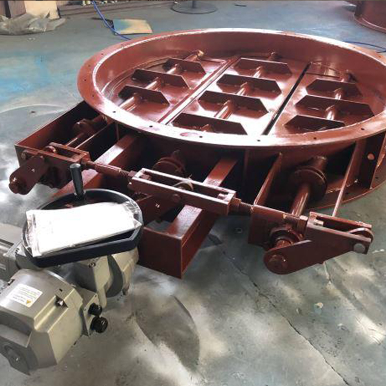
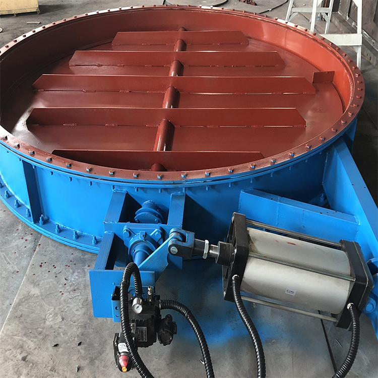
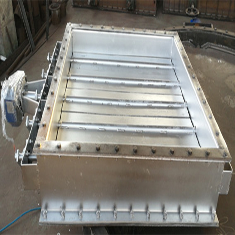
2. Adjust the air damper structure to a louver blade design, featuring an external linkage mechanism that simultaneously opens or closes multiple blades.
3. The guard blades are designed with an aerofoil structure, offering high rigidity, strength, and low resistance.
4. Multiple baffle vanes rotate to open or close in an "eight" shape, with the opening and flow rate adjusting linearly.
5. The driving method for adjusting the air damper is typically electric. The installation types of the electric valve actuator and the air damper are divided into two: direct coupling and crank bracket (local or remote) installations.
6. The electric valve actuator typically uses integrated mechanical and electrical products, featuring 4-20mA analog input/output signals, torque protection, and limit switches. It can be controlled locally or remotely, and the electric unit also includes a manual/electric switch function for installation, debugging, and maintenance purposes.
7. Adjust the connection method between the air gate and the pipe: three types of connections available - flange bolts, flange welding, or direct pipe welding.
Section 3: Technical Specifications
Product Model: TG-W×H×L
2. Applicable Medium: Cold air, hot air, flue gas, or dust-laden exhausted air.
3. Temperature Resistance: ≤400℃
4. Design Pressure Rating: 0.35 MPa
5. Adjustability: Linear adjustment of opening and flow.
6. Drive Method: Typically electric actuator.
7. Power and Control Requirements: User selectable.
Section 4: Range of Supplies
Including the wind door body, electric actuator, and other accessories.
V. Order Instructions
Provide pipeline cross-sectional dimensions and the installation location of the pipeline (either horizontal pipeline or vertical pipeline).
2. Opening and closing time: ≤60s (user selectable).
3. Flow medium, working pressure, working temperature.
4. Connection Method: Flange bolt connection or flange flat welding connection.
5. Operation Requirements: Electric or Manual.
6. The use and position of the air gate within the pipeline.
7. Supplier provides an installation general layout for confirmation prior to ordering.