


- AllProduct Category
-
Igniter
Flame Monitor
Flame Extinguishing Protection Device
Industrial Boiler Auto Ignition
Torch Ignition Control
Gas Ignition Burner
Torch Tip Series
Oil Gun & Propulsion Series


详情描述
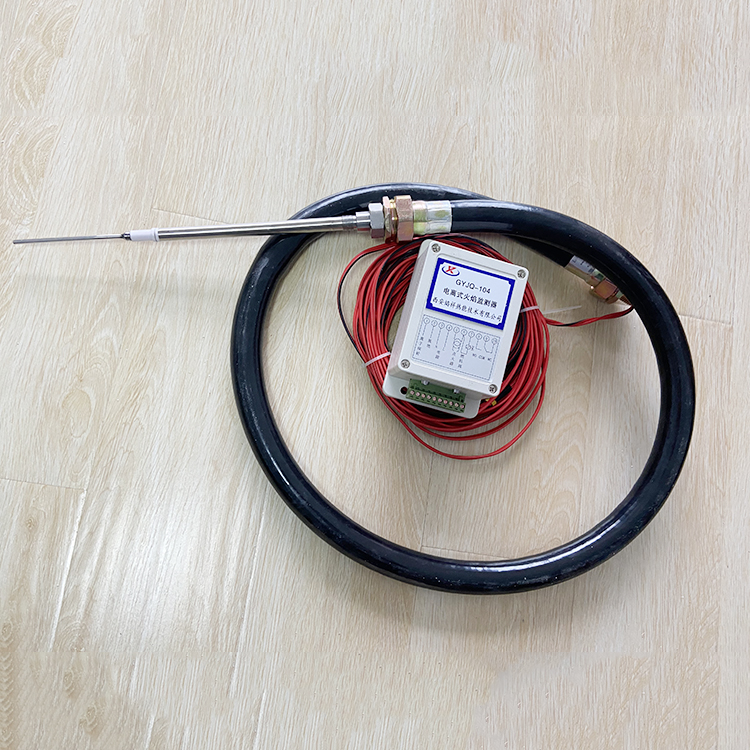
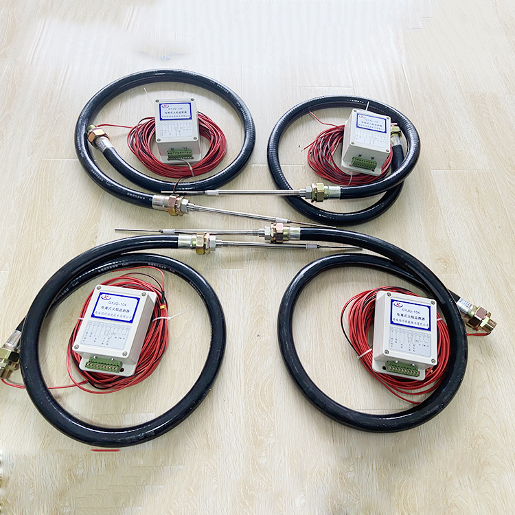
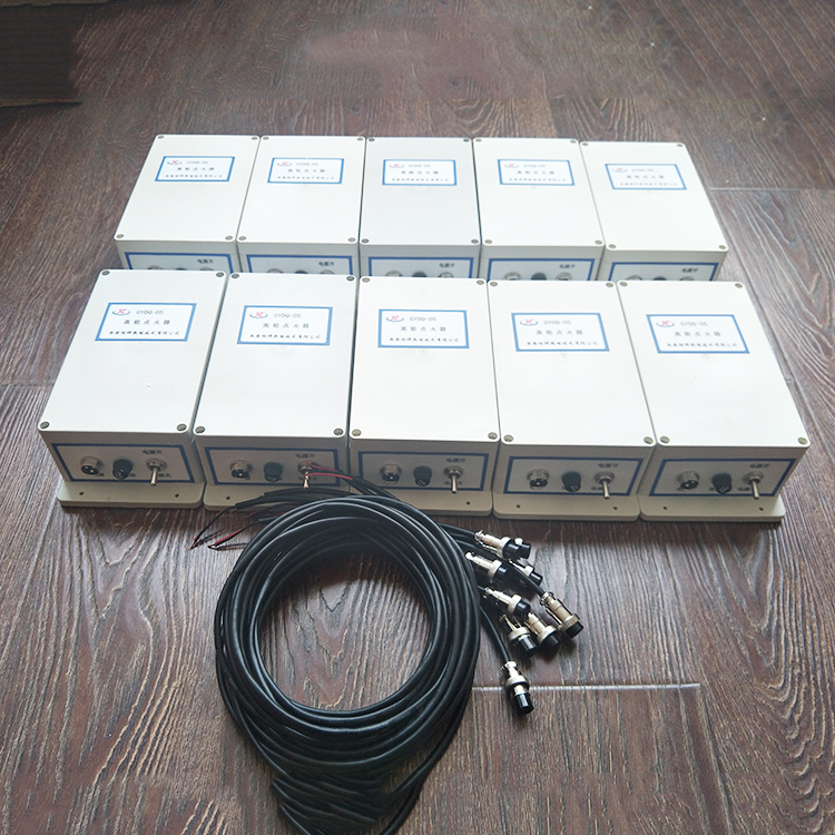
I. Overview:
The GYJQ-104 Ionization Flame Monitor is primarily used for flame detection in gas industrial burners. It is designed based on the principle of ion generation during fuel combustion, featuring imported integrated devices assembly. It employs high-speed photoelectric devices to transmit flame signals, offering high detection sensitivity and strong anti-interference capability. It can continuously monitor flames while eliminating the impact of carbon accumulation and wiring capacitance. It is sensitive to flames only and does not react to high temperatures.
II. Main Technical Parameters:
Power Voltage: 200~240V AC, 50/60Hz
Flame Probe: I (Ion-type)
Testing Response Time: <0.2S
Shut-off delay valve closing time: adjustable from 1 to 7 seconds
Ignition Time: 6 seconds
Probe Distance: ≤200 meters
Probe electrode temperature resistance: ≤1300℃ (long-term)
III. Monitor Operation Procedure:
Power on, the monitor outputs a timed ignition signal and an electromagnetic valve open signal. If ignition is successful, the ignition signal is closed after which the fuel valve open signal continues to be output. If ignition fails, both the ignition and fuel valve open signals are closed, and an unpowered alarm signal is output.
FourTerminal definitions for the monitor are as follows:

1Ion probe reception
2. Grounding
3Neutral wire
4Hotline
5, 6 Output ignition signal, 220V AC, 5A capacity
7, 8 Output solenoid valve open signal, 220V AC, 5A capacity
9, 10 output: normally open without power, closed with power
1011 Output is normally closed, open when power is on
V. Dimensions:
Shell: Waterproof ABS engineering plastic
Color: Grey
Dimensions: 158×90×41mm
Installation Dimensions: 182×52mm rectangular installation (length and width reserved: 200×100mm)
Mounting holes: φ7.0mm
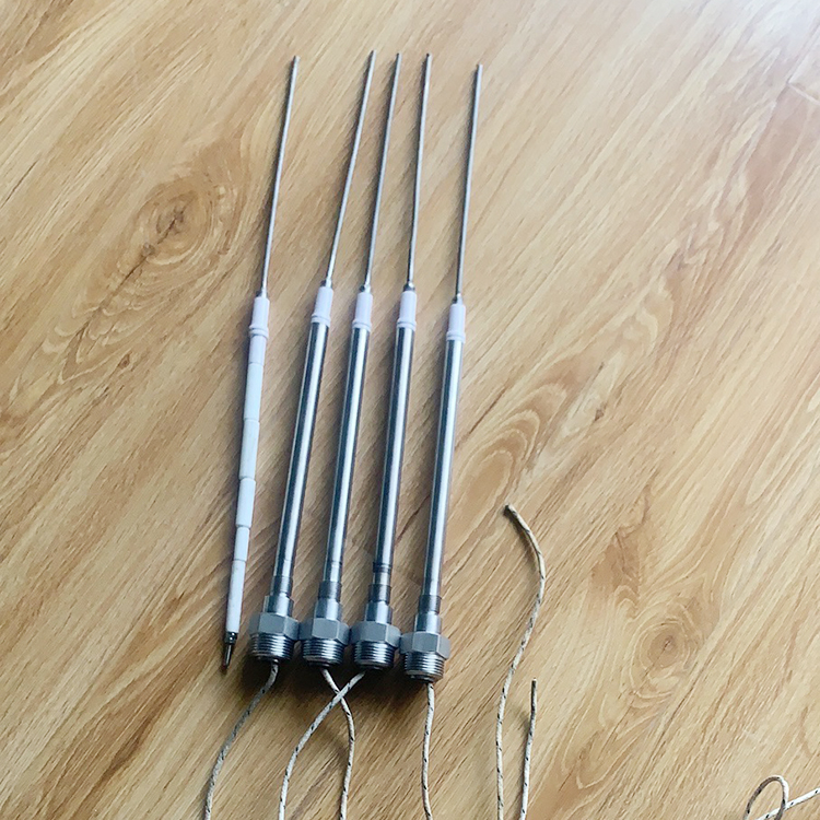
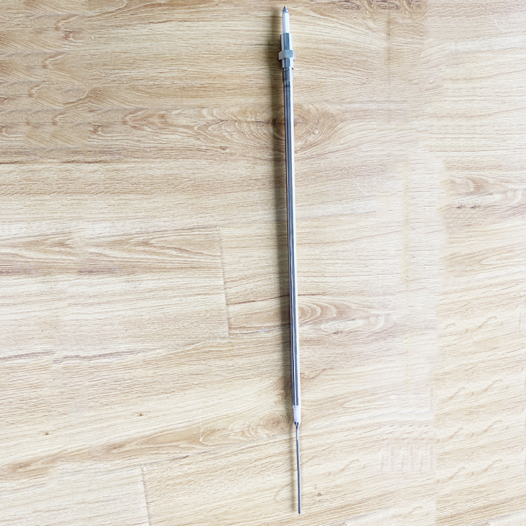
Ion probe installation thread: M14×1.25 (or custom-made to customer's request)
Ion probe diameter: φ12, inserted into flame zone Φ4
Ion probe electrode material: Pyromax high-temperature alloy
Ion Probe Length: Custom made to customer's specifications
The installation of the flame detection electrode must be able to contact the flame, with a detection hole diameter of Φ12.5mm, the electrode operates at a long-term working temperature of 1300°C, and no cooling is required.
Six: Installation
This monitor detects flames using a contact method. When installing the detection electrodes, ensure that the central electrode can touch the flame during monitoring. The central electrode of the detection electrode must be insulated from ground and should not come into contact with the metallic or refractory materials inside the burner.
The central electrode material of the detection electrode is made of a special high-temperature oxidation-resistant material. No ventilation or cooling is required during the installation of the detection electrode. The detection electrode can be used continuously at temperatures up to 1300°C. The operating temperature should not exceed 1400°C. Please select an appropriate location for installation.
This monitor uses single-electrode detection. If the user is using an isolated AC power supply, please ground one wire from the output of the isolated power supply and connect it to terminal 2 of the monitor.
Section 7:Tuning:
To enhance insulation performance and reduce wiring distributed capacitance, use wires with a voltage withstand rating of 500V for wiring. For the control room's detection lines, opt for aerial wiring as much as possible, avoiding trench wiring. The detection lines should not be mixed with other power lines or signal lines. Before connecting the power supply, please measure the resistance value between the detection output terminal and ground. The resistance value must be greater than 20MΩ. Use a multimeter for the measurement; do not use a megohmmeter to avoid damaging the controller.
In the absence of flame, open the module cover, plug in the power source, and gently turn the blue square sensitivity potentiometer on the upper left of the module clockwise until the relay engages and the green indicator light illuminates. Then turn the potentiometer counterclockwise until the green indicator light turns off, the relay just releases to the standard position. Turn it counterclockwise another two turns; at this point, the monitor is properly adjusted.
The central round potentiometer on the module adjusts the shutdown and valve closure time, ranging from 1 to 7 seconds. Clockwise adjustment extends the valve closure time, while counterclockwise adjustment shortens it. Set the valve closure time based on the stable flame burning condition, suitable for different operating conditions.
The monitor's sensitivity is pre-calibrated at the factory and generally does not require re-tuning.
Section 8: Troubleshooting
The burner flame is normal, and the center electrode can touch the flame, but the monitor indicates no fire.
A. Disconnect the power source and measure the insulation resistance between the test terminal and ground. If the resistance is less than 20 MΩ, it is due to severe carbon accumulation in the test electric high-temperature ceramic insulating tube or damage to the insulation of the test wire. If the ceramic tube has severe carbon accumulation, simply clean the carbon. If the insulation of the test wire is poor, replace the test wire.
B. If the ground resistance of the testing line exceeds 20 MΩ, it may be due to moisture absorption in the wire, causing an increase in distributed capacitance. Please measure the capacitance of the testing line to ground. If the capacitance is not greater than 0.1μF, please re-adjust the sensitivity potentiometer located at the upper left of the module. If the capacitance is greater than 0.1μF, consider shortening the distance between the module and the probe.
2. The burner has extinguished, but the monitor indicates a fire. This is due to the sensitivity potentiometer on the upper left of the module being over-adjusted. Please re-tune it.


