Busway, Busway manufacturer, Compact busway, Dense busway
0532-88888852


1. Transportation
After the formation of the dense busbar trunking products, they must be sealed with plastic film to prevent dust and water from entering, ensuring the integrity and undamaged condition of the dense busbar trunking. During transportation, the trunking must be stacked separately according to size to prevent sudden braking. When loading and unloading, great care must be taken to avoid damaging the terminal ends of the busbar trunking connectors, as this may impair contact and cause arcing and overheating, affecting the service life of the dense busbar trunking in electrical use.
During the storage of dense busbars on the construction site, the area must be dry, the ground free of debris, and the items elevated to prevent direct contact with the ground, thereby safeguarding the products from moisture seepage. When stacking, items should be gently placed to avoid heavy drops. The stacking height should be suitable for easy operation by construction personnel. The spacing between products should be sufficient for ventilation. The outer stack of dense busbars should be positioned slightly further apart from the inner layer, allowing the outer layer to slightly incline inward for stability, preventing the outer stack from shaking or collapsing, which could damage the products.
Busbars must not be lifted or tied with bare steel wire ropes; they must not be stacked arbitrarily or dragged on the ground. No other operations should be performed on the housing; it should be hoisted at multiple points and placed flat by forklifts without damaging the busbar. Busbars should be stored in a dry, clean, and non-corrosive gas-polluted warehouse. Soft packaging spacers should be placed between stacked busbars, and they should be properly stored.

2. Inspection
The equipment unboxing and counting should be conducted by the construction unit, supplier, and construction contractor, with proper records kept; the busway sections should have clear and complete marking, with no damage or deformation on the exterior, and no damage inside. The bus bolt connections should be flat, with no silvering defects, flaking, or uncovered areas, and the insulation resistance should meet standards. According to the busway layout diagram and packing list, inspect the busway, incoming line box, plug-in switch box, and accessories, ensuring their specifications and quantities meet requirements. Check if the busway housing is intact and undamaged, inspect the bolts for looseness, and ensure a reliable bolt connection. Verify that the busway interfaces are closed and securely locked. Measure the insulation resistance using a 500V megohmmeter, with resistance values of at least 10MΩ per section.
Installation
The installation of dense busbars must be measured on-site, with stringent requirements for the length of the conduit. The height of the plug-in switch box for busbars should also be determined according to the design. When fire protection distribution lines are installed underground, they should be placed within non-combustible structures, with the protective layer thickness not less than 30mm. For exposed installations, fire-resistant coatings should be applied to metal pipes or conduits, as these materials do not inherently possess fire-resistant properties. When using cables with non-flammable insulation and sheath, metal pipes or conduits are not required in the shaft, but the cables must pass through pipe or conduit protection when crossing the shaft floor. The gaps at both ends of the pipes and conduits should also be sealed.
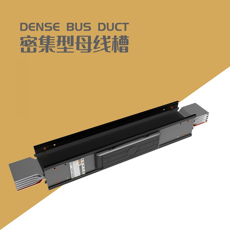
密集型 busway connection
Busbar channel brackets must be securely installed. Busbars should be correctly positioned according to section numbers, phase sequence, numbering, direction, and installation markers. When connecting sections, adjacent busbar channels should align, and after connection, the conductors of the busbar channel should not be subjected to mechanical pressure.
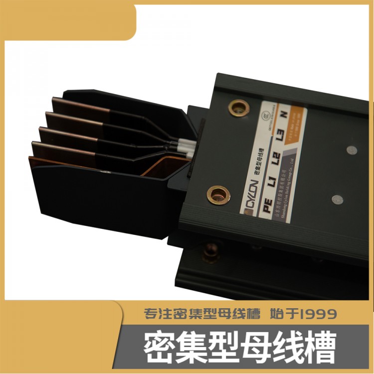
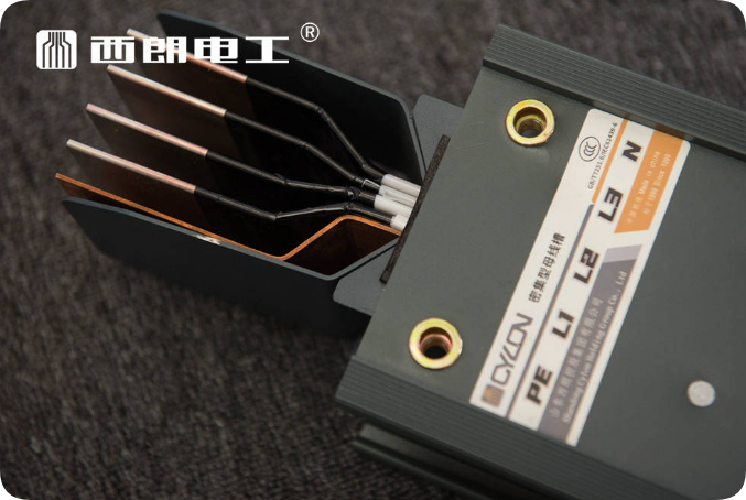
Installation Steps for Connection: First, check the conductor connection surface and the terminal connector at one end of the busbar channel for any dents or damage, and confirm there are none before beginning to connect the two sections of the busbar channel to the terminal connector. Insert the conductor of the busbar channel into the terminal connector 60mm, and then tighten it with a torque wrench to ensure it is properly seated. For the connecting type busbar channel, align the end sections of the two busbar conductors to be connected in parallel, and then insert the copper connecting strips and insulating spacers into the gaps between the busbar terminal ends (place one copper connecting strip on each side of each phase busbar, and insert an insulating spacer between the copper connecting strips). After confirming there are no issues, thread in the insulating bolts, and make sure the copper connecting strips and spacers are properly seated, then tighten the bolts.
![]()
After the busbar槽 is fully connected, the grounding resistance must be checked using a multimeter in the 1Ω range, with the resistance value being less than 0.1Ω to meet grounding requirements.
Busway trough horizontal installation
Busbars should be installed horizontally at a height not less than 2.2 meters from the ground, except when installed in electrical专用 rooms (distribution rooms, motor rooms, electrical shafts, technical floors, etc.). The distance from the busbar edge to the wall edge should be no less than 0.1m, and the distance above the floor, ceiling, and beam bottom should also be no less than 0.1m. For two horizontally adjacent busbars: the center distance between busbars should not be less than 0.35m, and the edge spacing should not be less than 0.1m. The spacing between support points for horizontally laid busbars should not exceed 2.5m (for high-strength busbars in large-span workshops, the spacing may exceed 6m). When horizontally installing busbars on supports or hangers, use horizontal fixed pressure plates for fixation. The connection points of the busbars should not be at wall penetration points, and when installing wall penetration holes for busbars, there should be no wastewater or debris entering the busbar interior.
Busway connector feed holes should be located in safe, reliable areas with easy installation and maintenance. When the straight laying length of the busway exceeds 60 meters, expansion joints should be installed. At the locations where the busway crosses the expansion or settlement joints of the building, settlement (expansion) joints should be set.
(Busway channel vertically installed)
Busbar channel should be vertically installed with the joint distance from the ground not less than 0.7m, and the joint distance from the floor not less than 0.3m. The distance from the back of the busbar channel to the wall edge should not be less than 0.1m. When the busbar channel is vertically installed between floors, the single straight length of the busbar channel should not exceed 3.6m; for floors exceeding 3.6m in a single layer, they should be made in two sections or more, and intermediate fixed brackets should be installed between floors. The connection points of the busbar channel should not be at the point where it passes through the floor. When installing the busbar channel through the floor, there should be no wastewater or debris entering the interior of the busbar. The busbar channel plug-in power feed holes should be located in a safe and reliable position, as well as convenient for installation and maintenance. After the plug-in box is installed, the height of the bottom of the box should not be less than 0.9m.
When installing busbars vertically, the spring brackets should be mounted onto the busbar first, followed by securing the busbar and spring brackets to the channel support架, tightening the spring nut of the bracket. After installing 4-5 layers, unscrew the nuts from top to bottom layer by layer to allow the weight of the busbar to naturally rest on the bracket springs. Once the busbar connections are tightly secured, the bend should not exceed 1 degree. For two vertically adjacent installed busbars, the center distance between them should not be less than 0.35m, and the side spacing should not be less than 0.1m.
Busbar channel straight laying length exceeding 60m should have an expansion (伸缩) joint installed.
(4) Connector Box Installation
Before installing the busbar slot connector box, the safety guard at the busbar slot opening should be removed. Prior to installing the busbar slot connector box, the switches inside the box should first be pushed to the OFF position; then, insert the connector box pins according to phase.
Contact us

Service Hotline
13061252393
Company Telephone
0532-88888852

Address
Qingdao City, Chengyang District; 7th Floor, Shandong Huatong Building, at the intersection of Guangsheng Road and Juxian Bridge Road
b2b.china9.net © Zhongshang 114 Hebei Network Technology Co., Ltd.Address: Room 6009, Oriental New World Center, No.118 East Zhongshan Road, Qiaoxi District, Shijiazhuang City, Hebei ProvincePlatform Service Hotline: 4006299930