
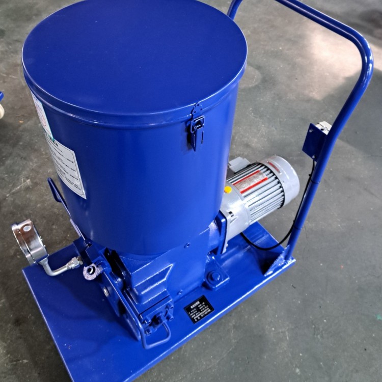
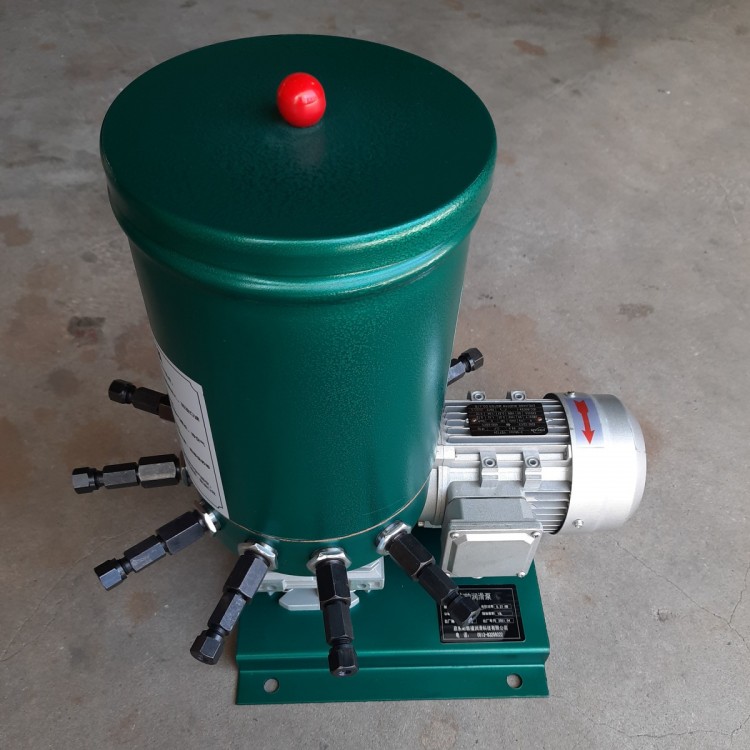
 HB-P Electric Lube Pump - HB-P400
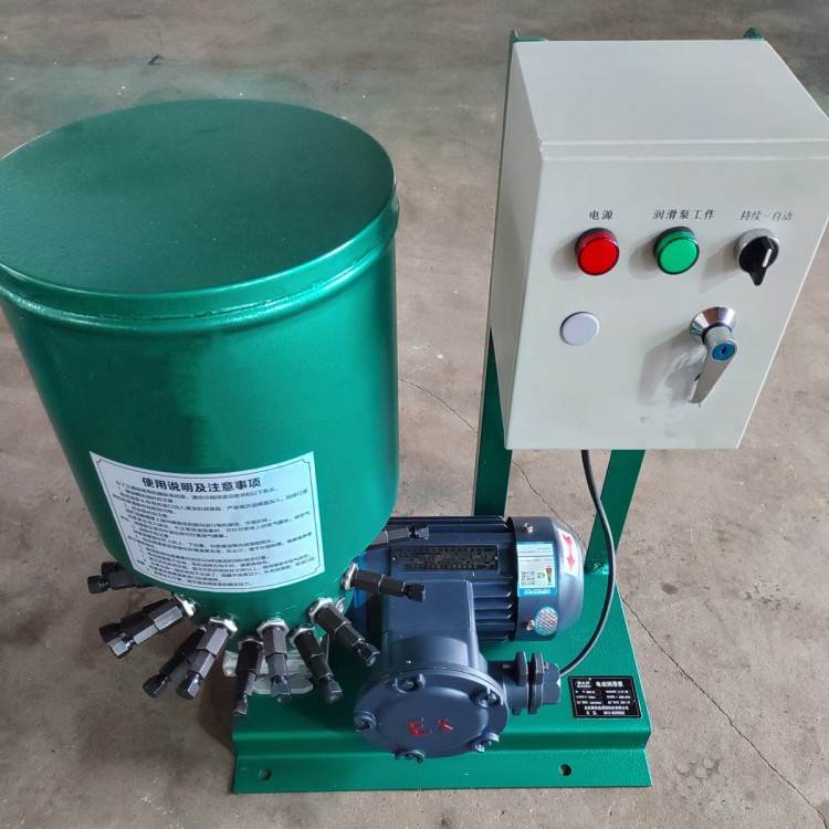
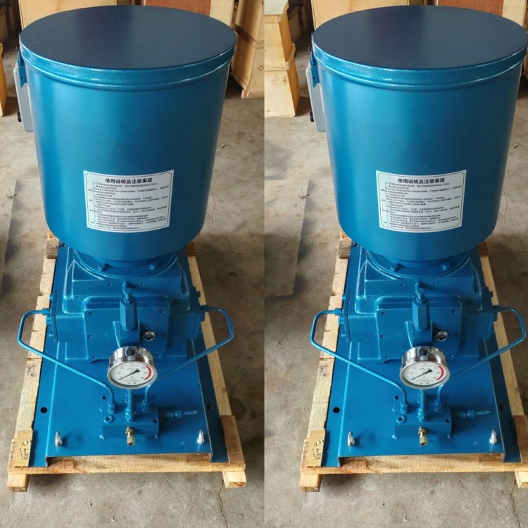 HB-P Electric Lubrication Pump - DRB-P430
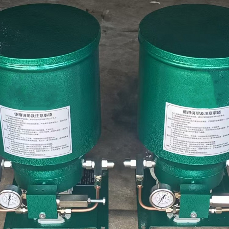
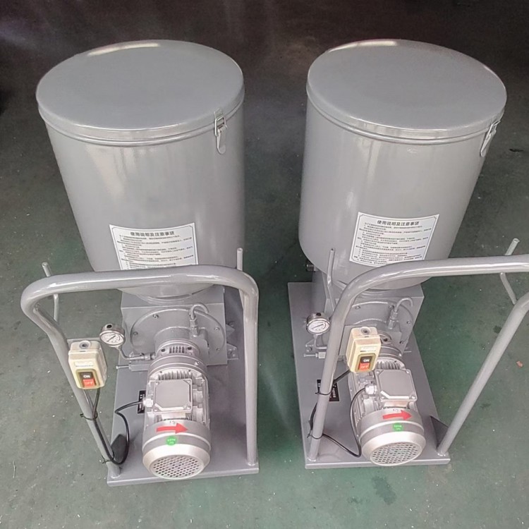 DRB-P Electric Lubrication Pump - DRB9-P365Z (P/M)
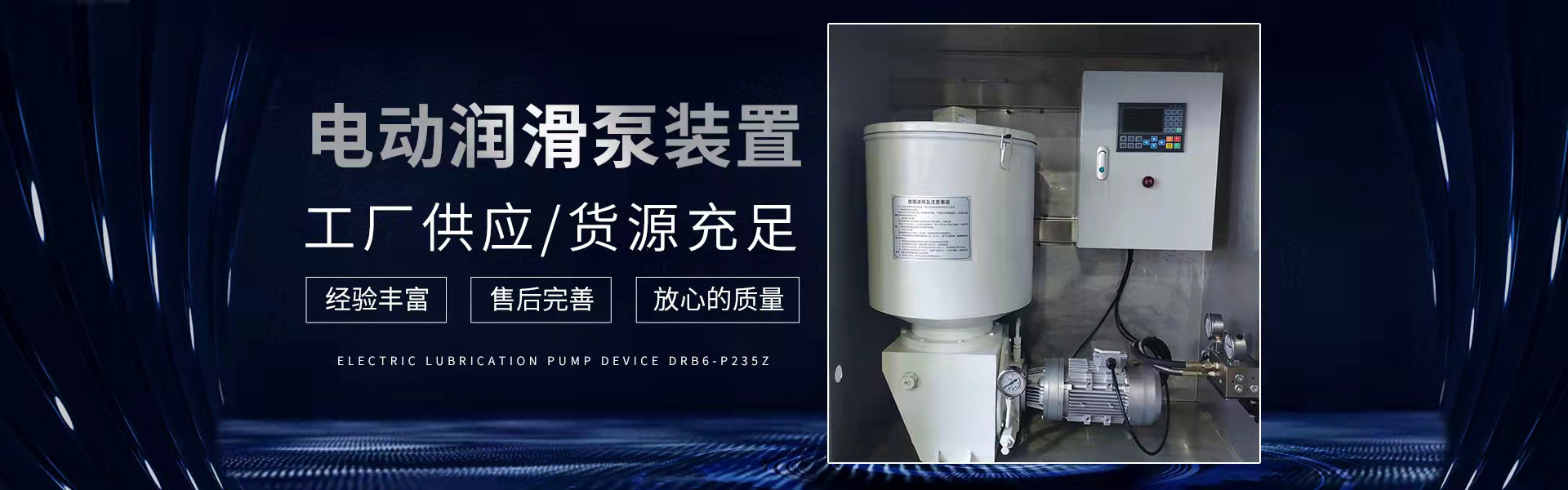
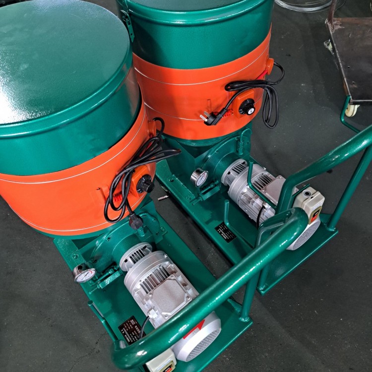 DRB-P Electric Lube Pump - DRB6-P235Z
 DDB Series Multi-point Grease Pump - DDB-10
 DDB Series Multi-Point Oil Mist Pump - JNB-10S
 DB-N Single-Line Lubrication Pump - DB-N25
Product Details
Electric Lubrication Pumps | Centralized Lubrication Systems | Multi-point Oi...
产品Price 40.00/Piece
最小起订Quantity:1 Piece 供货总Quantity: 99999 Piece


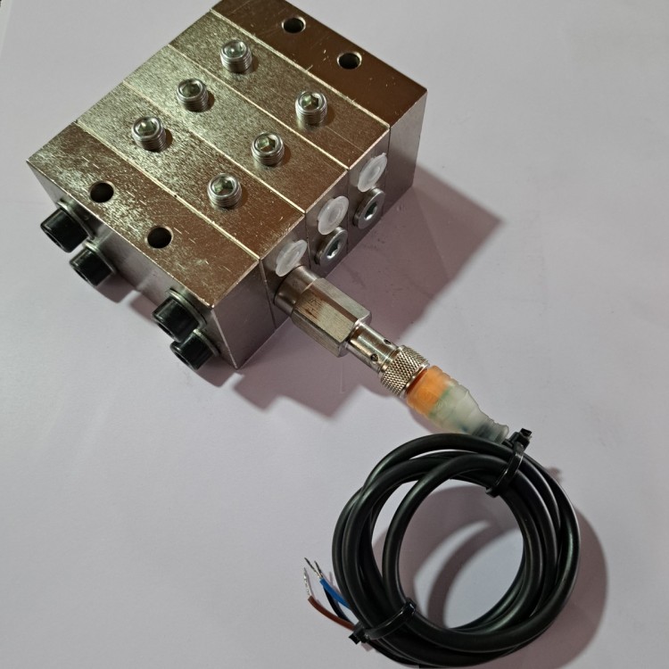
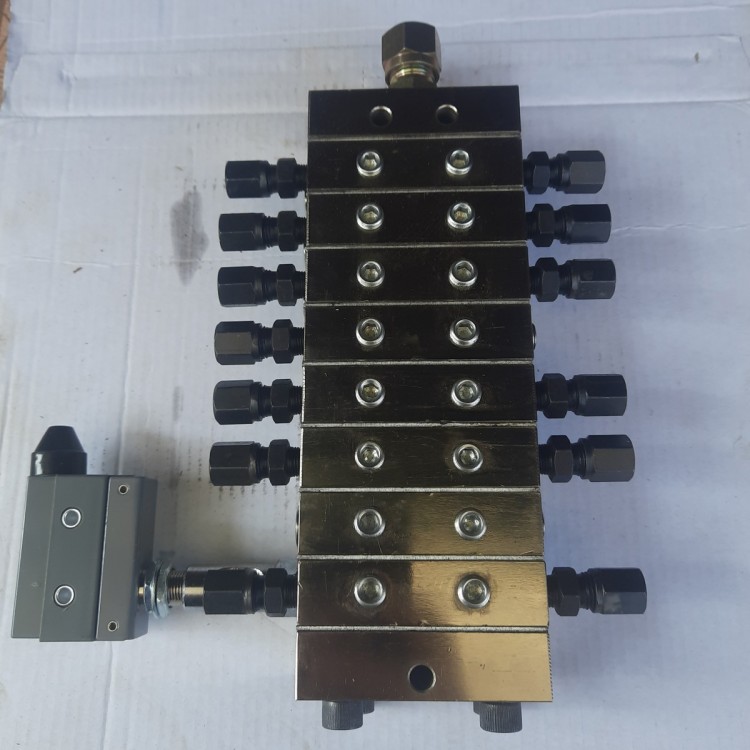
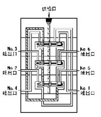
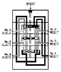
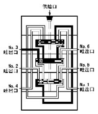
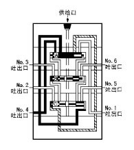
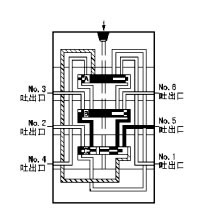
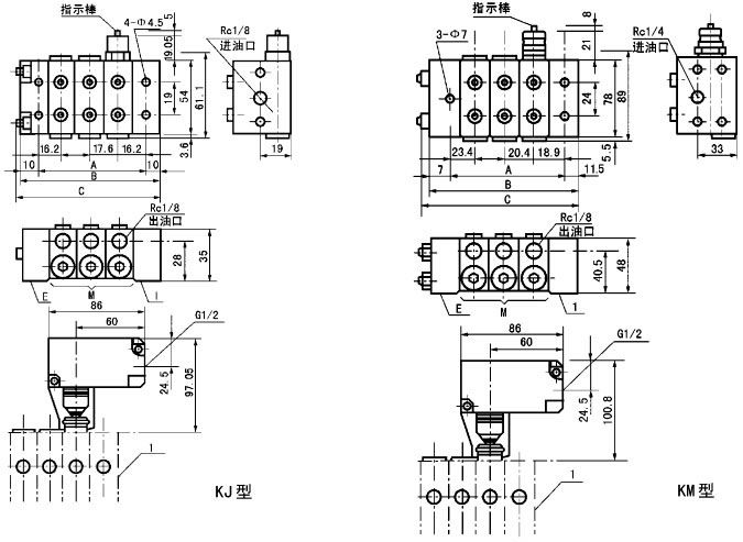
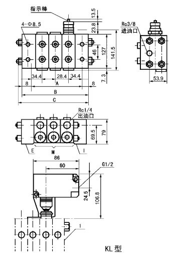
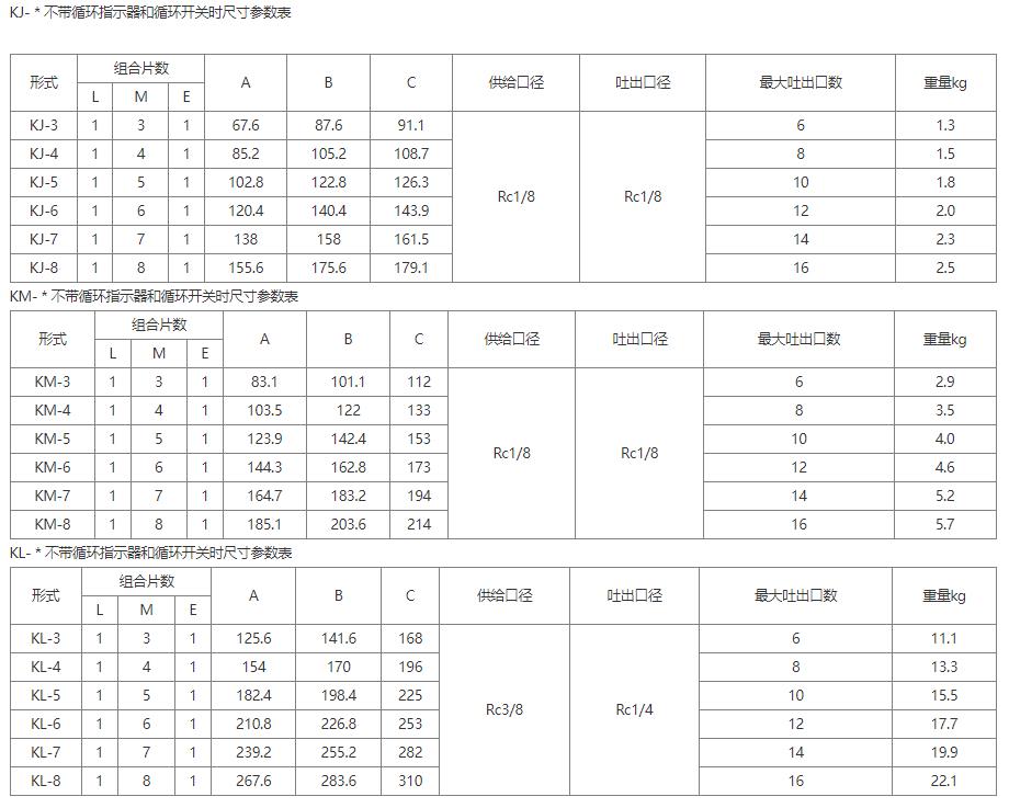
KJ, KM, KL Series Single-Line Progressive Distributors (7-21 MPa) I. Overview KJ, KM, KL series single-line progressive distributors, suitable for systems with dense lubrication points, varying oil consumption, and frequent oiling in a single-line concentrated lubrication system. They are used to form a parent-child distribution system for zone control and lubrication. The KJ, KM, KL series single-line progressive distributors are composed of a supply body, end body, and intermediate bodies (3-8 pieces, depending on design requirements) made of medium-carbon alloy structural steel. The normal outlet of the distributor is set on both sides, with auxiliary outlets also provided. Non-return valves are installed inside the oil outlets of each intermediate body, effectively preventing the backflow of grease due to the back pressure of the lubrication points, ensuring the precise and quantitative supply of grease to each outlet. II. Technical Specifications Applicable to greases with a penetration not less than 265 (25°C, 150g) 1/10mm or lubricating oils with a viscosity grade greater than N120: Operating temperature range: -10℃ to 80℃. III. Operation Description 1. The lubricant, pressurized by the lubrication pump, flows into the supply port and moves the pistons A, B, and C according to the arrow direction in the diagram. At this point, the left chambers of pistons A and B remain stationary in the right position due to the oil pressure, while the right chamber of piston C receives pressure, causing the oil to start moving to the left. 2. The incoming lubricant pushes piston C to the left, forcing lubricant in the left chamber towards the NO.1 outlet through external piping to the lubrication point. When piston C reaches the left limit, lubricant begins to enter the right chamber of piston B. 3. The incoming lubricant pushes piston B to the left, forcing lubricant in the left chamber towards the NO.2 exhaust outlet through external piping to the lubrication point. When piston B reaches its left limit, lubricant begins to enter the right chamber of piston A. 4. The incoming lubricant pushes piston A to the left, forcing lubricant in the left chamber towards the No.3 exhaust outlet, which is then sent to the lubrication point through external piping. When piston A reaches its left limit, lubricant begins to enter the right chamber of piston C. 5. The incoming lubricant pushes piston C to the right, forcing lubricant in the right chamber towards the NO.4 exhaust outlet through external piping to the lubrication point. As piston C moves to the right limit, lubricant begins to enter the left chamber of piston B. 6. The incoming lubricant drives piston B to the right, pushing lubricant from the right chamber towards the NO.5 outlet. It is then sent to the lubrication point through external piping. As piston B moves to its rightmost limit, lubricant begins to enter the left chamber of piston A. 7. Inflowing lubricant drives piston A to the right, pushing lubricant in the right chamber towards the No.6 outlet. It is then sent to the lubrication point through external piping. When piston A reaches the right limit, it returns to the initial state 1 and continues to repeat the above action. Four: Dimensions Section 5: Model Description Six. Overpressure Indicator Mounted on the distributor's preparatory outlet, the indicator slightly protrudes outward when the pressure rises above the specified value due to a lubrication point or pipeline blockage. Through the fault signal emitted by the system, the blocked section can be directly located by checking if the indicator has protruded on-site. Section 7: Overflow Indicator Installed on the outlets of all distributors at locations prone to blockages in harsh environments, when a lubrication point or pipeline becomes blocked, the pressure abnormally rises above the specified value. The lubricant supplied to the blocked point of the distributor overflows out through the overflow port. Upon inspection, the overflow point indicates the blocked fault location. Only applicable to continuous operation sections; not to interfere with the operation of other distributors. Exhalation Mark Description: T: Standard type with two outlets, respectively from... Oil outlet on both sides of the intermediate. S: One outlet (T-type two outlets connected), oil Quantity is twice that of the T-type, oil can be discharged from either the left or right side. LC: No left outlet; the left outlet is viewed from the direction of the oil intake Combine oil volume with the adjacent出口 section. RC: No right outlet, viewed from the direction of the fuel intake Combine oil volume with the adjacent export section. 2C: No exports; both left and right exports are adjacent to the next Combined oil volume for sheet export. Section 8: Order Instructions Please order with the complete model number and provide a connection diagram. KM-3 (15T + 25T2C + 30S) R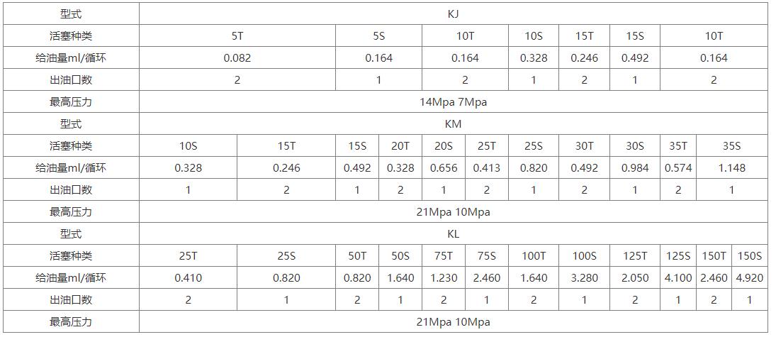


Phone Consultation