
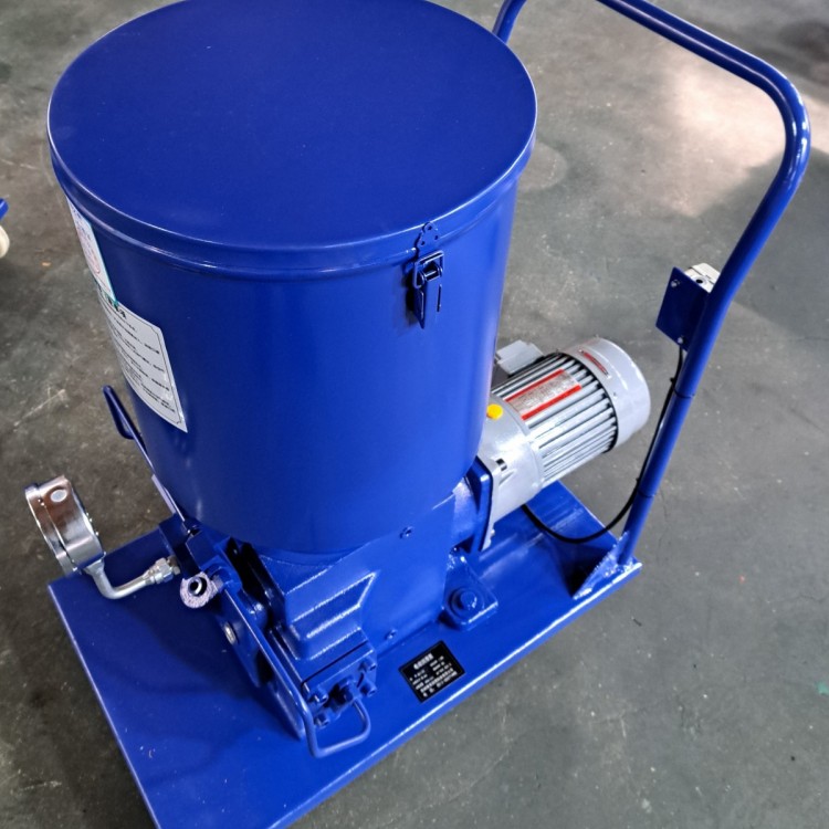
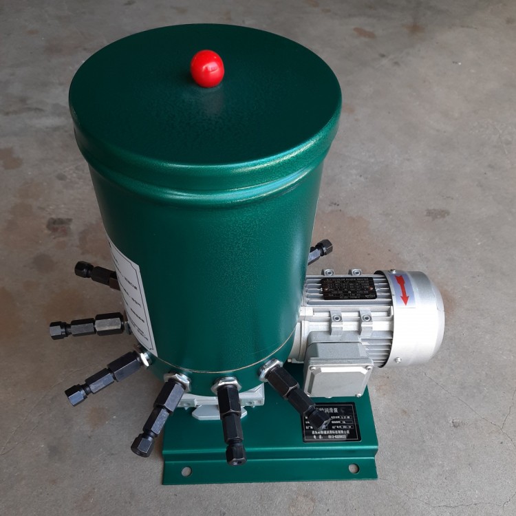
 HB-P Electric Lube Pump - HB-P400
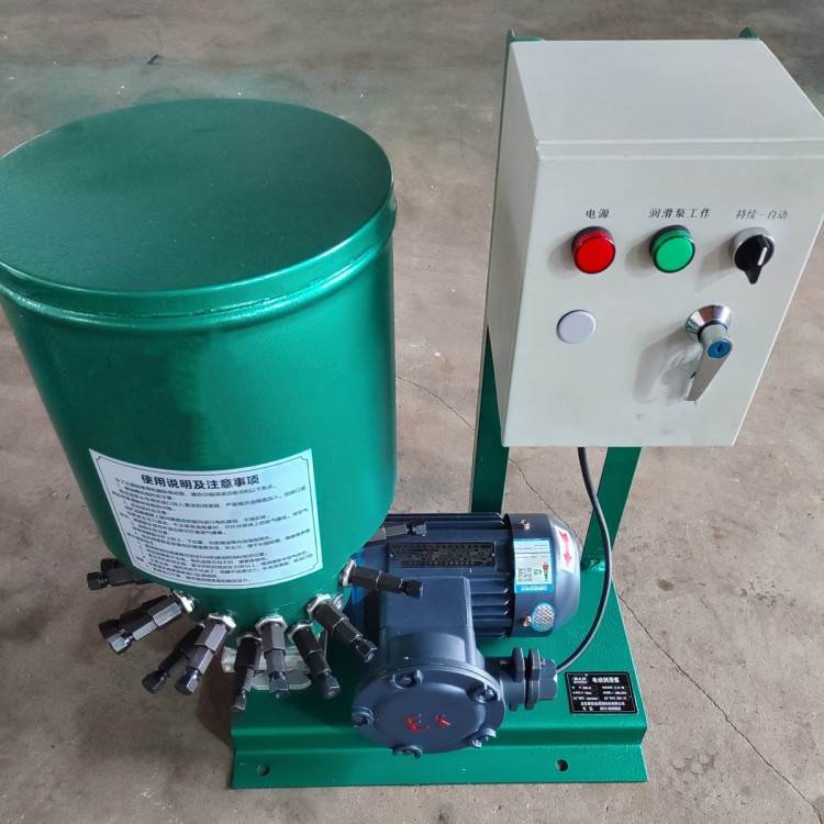
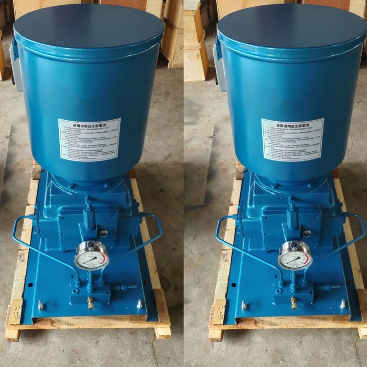 HB-P Electric Lubrication Pump - DRB-P430
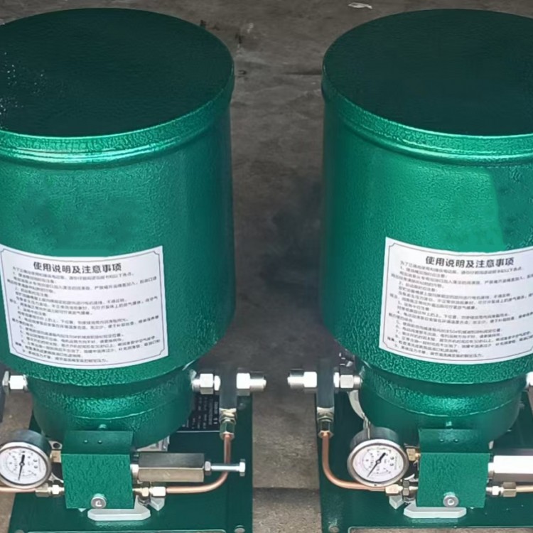
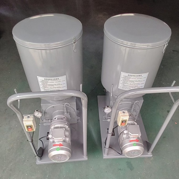 DRB-P Electric Lubrication Pump - DRB9-P365Z (P/M)
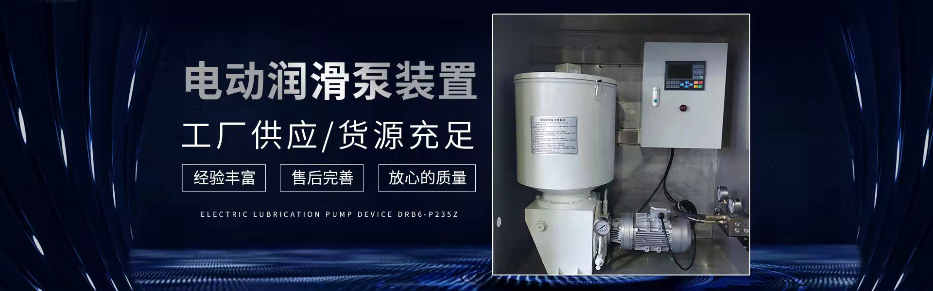
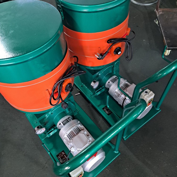 DRB-P Electric Lube Pump - DRB6-P235Z
 DDB Series Multi-point Grease Pump - DDB-10
 DDB Series Multi-Point Oil Mist Pump - JNB-10S
 DB-N Single-Line Lubrication Pump - DB-N25
Product Details
Electric Lubrication Pumps | Centralized Lubrication Systems | Multi-point Oi...
产品Price 450.00/Piece
最小起订Quantity:1 Piece 供货总Quantity: 99999 Piece


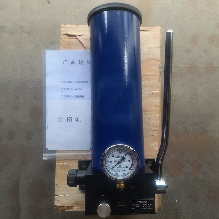
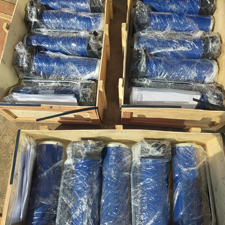
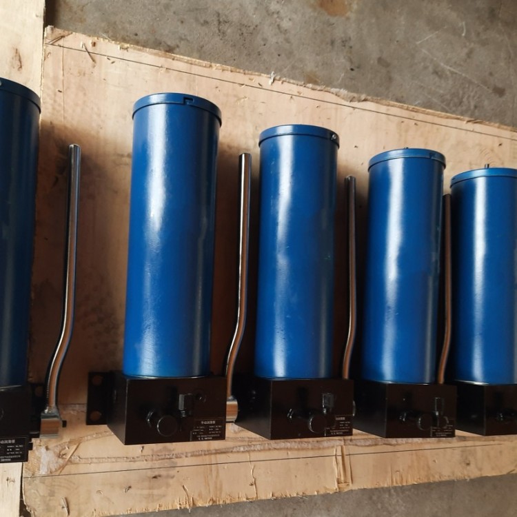
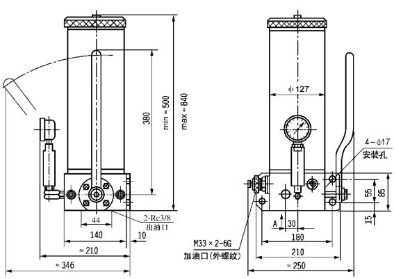
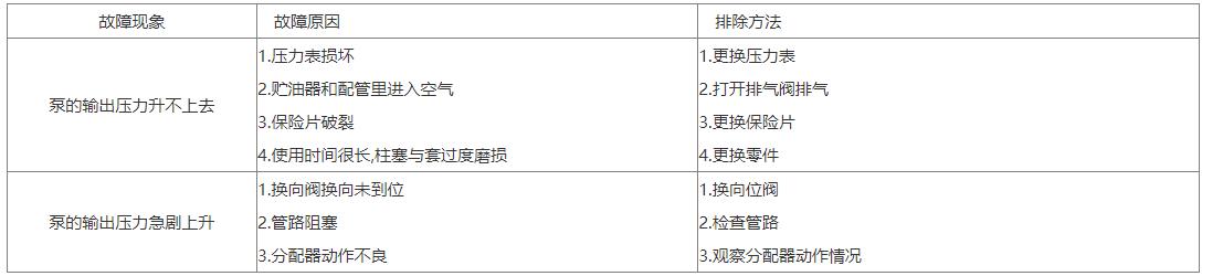
SGZ-8 Manual Lubrication Pump (10MPa) I. Terms of Use This manual lubrication pump is a small unit operated by hand to expel grease, which can be directly mounted on the machine's wall panel or frame. It is designed to be used in conjunction with a double-line lubricator to form a manual centralized lubrication system at the terminal. A device for supplying grease to a centralized dry oil lubrication system, suitable for single small machinery with a lower lubrication frequency (typically an oiling interval of 8 hours or more), piping (DN20) length not exceeding 35 meters, and no more than 50 lubrication points. II. Technical Specifications Lubricant with a penetration of 265 (25°C, 150g) 1/10mm is used, suitable for environmental temperatures of 0°C to 40°C. III. Working Principle Manual lubrication pump feeding is achieved by manually turning the handle, which drives a small gear to make a ratchet-type plunger 2 reciprocate. When the plunger is at the right-hand extreme position (as shown in the right figure), the volume of the left oil cavity increases, creating a vacuum, and the grease in the reservoir is drawn into the left oil cavity due to atmospheric pressure and piston pressure. As the plunger moves to the left, it compresses the grease, lifting a one-way valve 4 and directing it through a directional valve into the main oil line II. Meanwhile, the volume of the right oil cavity on the plunger increases gradually, drawing in grease. When the plunger reverses and moves to the right, the oil cavity filled with grease becomes smaller, compressing the grease again and lifting a one-way valve 3, directing it through the directional valve into the main oil line II. The direction change during the feeding process is achieved through a directional valve 6. Pulling the directional valve handle releases grease from line II; pushing it pushes grease out from main oil line I. Four: Dimensions Section 5: Model Description Six: Operation Method Push the directional valve handle to the full position, supplying fuel to main line I. 2. The handle moves forward and backward, causing the pressure gauge needle to fluctuate, indicating that the oiling system is in action. 3. The pressure gauge on the pump indicates a steady increase in pressure value, proving that the oil feeder in the system has completed all operations. 4. Turn the directional valve handle to change direction, allowing main pipeline II to supply fuel, and proceed as per Section 2.3. 5. Rotate the directional valve to relieve pipeline pressure, prepare for the next cycle, and pull the handle into a vertical position. Section 7: Instructions for Use 1. Manual lubrication pumps should be installed vertically, with enough space above and around the pump for the indicator rod to rise and for lubrication replenishment. When used outdoors or in harsh environments, they should be placed within a protective cover. 2. Add lubricant to the oil storage cylinder using a dedicated manual or electric oil pump from the lubricant pump's filling port. 3. The filter screen of the pump oil filling port should be regularly inspected and cleaned. 4. Do not operate the handle if there is no lubricant in the oil reservoir; top up with lubricant promptly when the oil level is low to prevent air intake. Section 8: Common Faults and Troubleshooting


Phone Consultation