
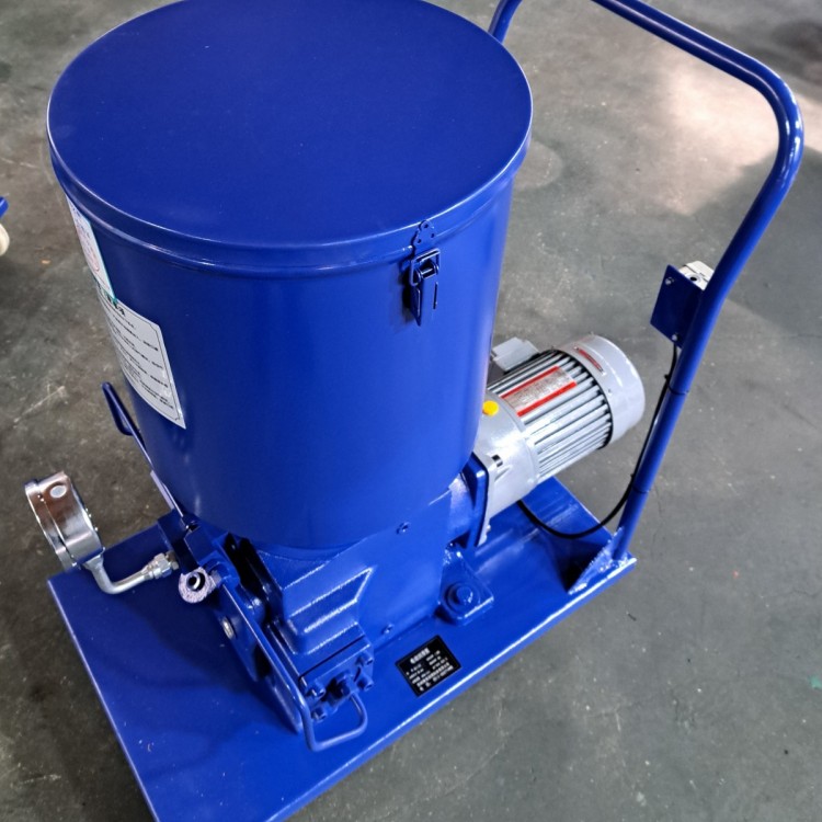
 HB-P Electric Lube Pump - HB-P400
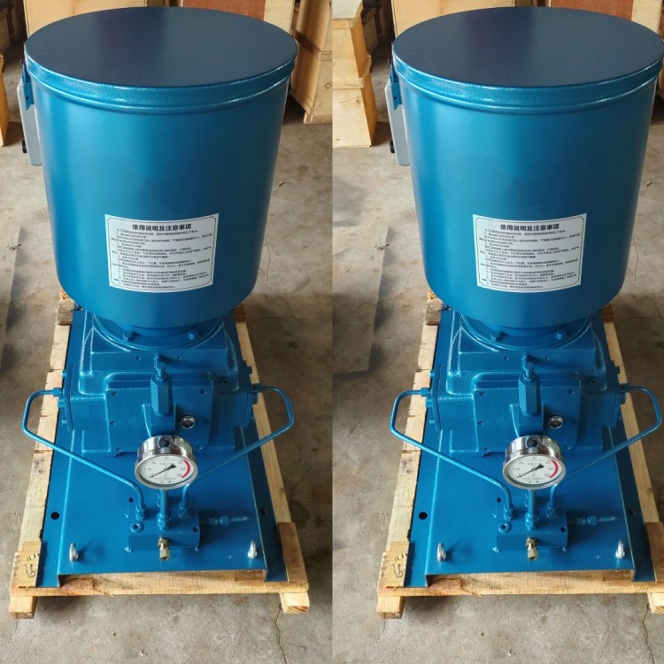 HB-P Electric Lubrication Pump - DRB-P430
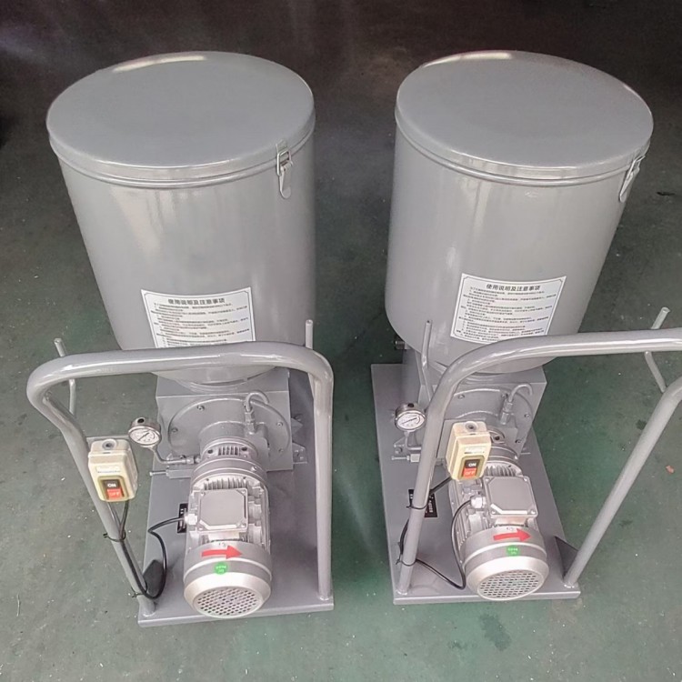 DRB-P Electric Lubrication Pump - DRB9-P365Z (P/M)
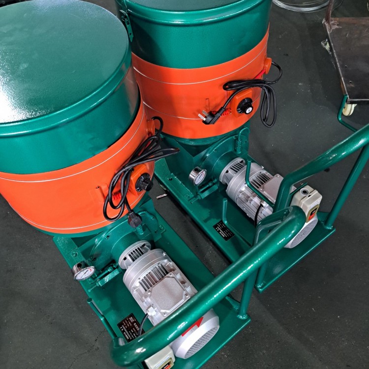 DRB-P Electric Lube Pump - DRB6-P235Z
 DDB Series Multi-point Grease Pump - DDB-10
 DDB Series Multi-Point Oil Mist Pump - JNB-10S
 DB-N Single-Line Lubrication Pump - DB-N25
Product Details
Electric Lubrication Pumps | Centralized Lubrication Systems | Multi-point Oi...
产品Price 800.00/piece
最小起订Quantity:1 piece 供货总Quantity: 99999 piece


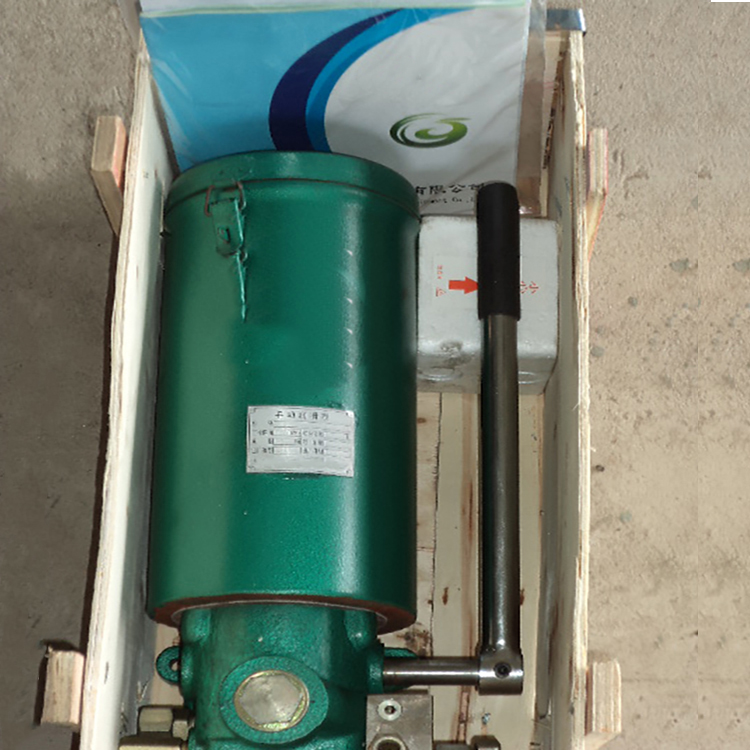
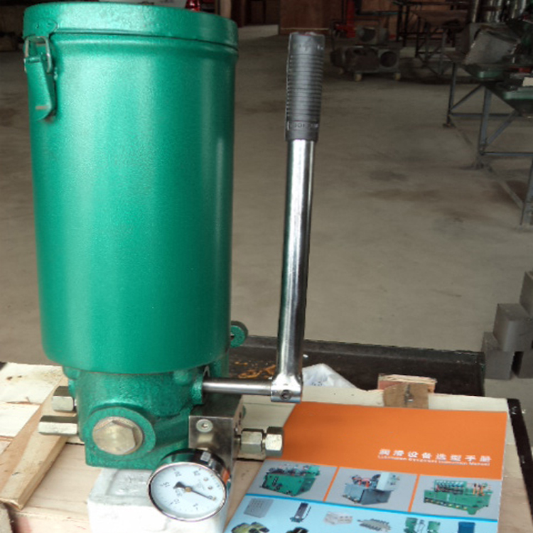
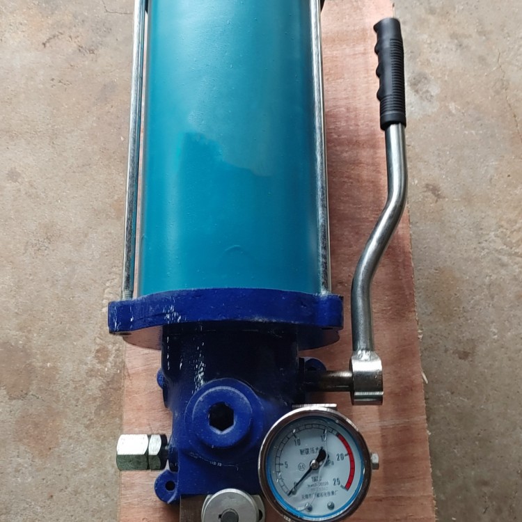
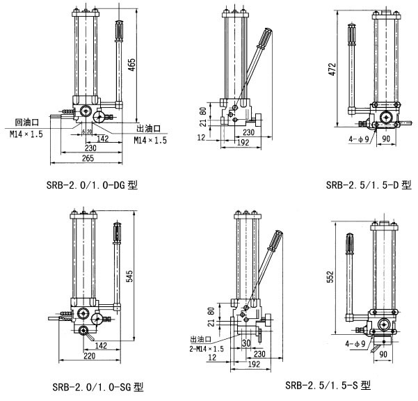
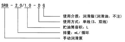
SRB Series Manual Lube Pumps (20MPa, 10MPa) I. Terms of Use A manual lubrication pump is a small lubrication pump operated by a manual lever handle to expel lubricant. It can be directly mounted on the machine's panel or frame. The basic model can directly be combined with a single-line distributor to form a manual single-line centralized lubrication system; the basic model with a reversing valve and a dual-line distributor can be assembled to create a manual dual-line terminal centralized lubrication system. This pump is suitable for single small machinery with low lubrication frequency (typically an oiling interval of 8 hours or more), piping with a DN10 length not exceeding 50 meters, and no more than 40 lubrication points, serving as a centralized lubrication system to supply lubricants. II. Technical Specifications The product uses grease with a penetration of 265 (at 25°C, 150g) 1/10mm (NLGI 0#-2#) and a lubricant with a viscosity grade above N68, suitable for ambient temperatures ranging from -10°C to 40°C. Section 3: Dimensions IV. Model Marking Instructions V. Working Principle The manual lubrication pump operates by manually turning the handle, which drives gear piston 2 through gear 1 to achieve reciprocating motion for lubrication. When the piston reaches the right extreme position as shown, the volume of the left oil cavity increases, creating a vacuum. The lubricant in the reservoir is then drawn into the left oil cavity of the piston by the spring and piston plate. As the piston moves to the left, the lubricant is forced into channel Ⅰ and pushes the slide valve 4 to the right extreme position, lifting check valve 5 to expel it from the outlet. At this point, the volume of the right oil cavity at the piston's right end gradually increases, drawing in lubricant. When the piston returns to move rightward, the lubricant-filled cavity decreases in volume, squeezing lubricant into channel Ⅱ, pushing slide valve 4 leftward, lifting check valve 5 to expel it from the outlet. A directional valve is installed at the bottom of the pump; by turning the directional handle to either extreme position, dual-line lubrication supply is achieved. Section 6: Operating Procedures Single-line type: 1. Push the indicator rod of the return oil gauge. 2. The handle moves forward and backward, and the pressure gauge needle fluctuates, proving that the system distributor is applying oil. 3. The indicator rod of the return oil gauge is fully extended, indicating that the system distributor has completed one oil distribution cycle. 4. Push the oil return indicator rod to prepare for the next cycle. Double-line type: 1. Turn the directional valve handle to the left position, supplying oil to main pipeline I and releasing load from main pipeline II. 2. The handle of the reciprocating pump moves front and back, and the pressure gauge needle fluctuates, indicating that the system distributor is supplying oil. 3. The pressure gauge on the pump indicates an increase in pressure and remains stable, proving that the system distributor has completed its first cycle. 4. Rotate the directional valve handle to the right position, supplying oil to Main Line II and de-energizing Main Line I. Follow steps 2 and 3 to complete one cycle of the system operation. 5. Shift the directional valve to release pressure from Pipe II, preparing for the next cycle. Section 7: Instructions for Use 1. Manual lubrication pumps should be installed vertically, with space allowed above and around the pump for the indicator rod to rise for lubrication. When installing in outdoor or harsh environments, the pump should be placed within a protective housing. 2. Do not operate the handle if there is no lubricant in the oil storage cylinder. 3. Add lubricant to the oil storage cylinder using a dedicated manual or electric oil filling pump through the filling port; lubricant is added from the top of the cylinder. 4. Do not exceed the pump's nominal pressure when applying pressure. 5. Safety insurance strips must not be used in pairs overlapping; substitution with other materials is not permitted. 6. The function of the oil return indicator on a single-line pump is for the operator to observe the movement of the indicator piston to determine the lubrication condition of the oil supply system. During use, first calculate the required oil supply for each lubrication point, set up the distributor, and connect an additional oil outlet on the main distributor to the oil return port of the manual lubrication pump, allowing the lubricant to return to the indicator. If the accumulated oil returned reaches 3.28 mL, the piston rod of the indicator extends fully, indicating that each lubrication point has completed a cycle of oil supply as needed. It is then necessary to stop the oil supply and push the indicator rod of the oil return indicator back in. For example in this image: Each bearing requires 3.2ml, 9.8ml, 9.8ml, and 6.5ml of oil every 4 hours, distributed by the M-3 distributor (10T-30T-20T). When operating the manual lubrication pump, the lubricant returns from an outlet on the 10T manifold to the pump's回流indicator until the plunger pushes out, indicating that the required oil quantity has been delivered to each bearing.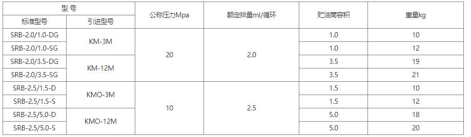


Phone Consultation