Mechanical Manufacturing: Mining machinery manufacturing, mechanical parts, and component processing
13623818504


From the day of the product purchase, our services kick off. After communications and negotiations between both parties, a specific on-site planning agreement is signed. Hongxin Mining will dispatch technical personnel to implement according to the agreed-upon timeline and specific requirements. Based on the client-provided dimensions of the equipment entry site and the content to be planned, Hongxin Mining will provide the client with an "on-site layout plan" and "equipment foundation plan" within a short period. The plans will be sent to the client via fax or mail, and after confirmation of accuracy, construction will proceed according to the plans.
Installation and Adjustment
Installation
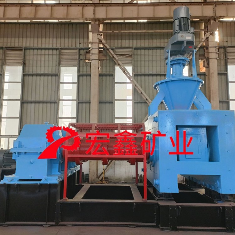
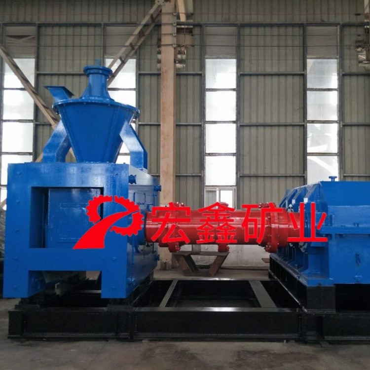
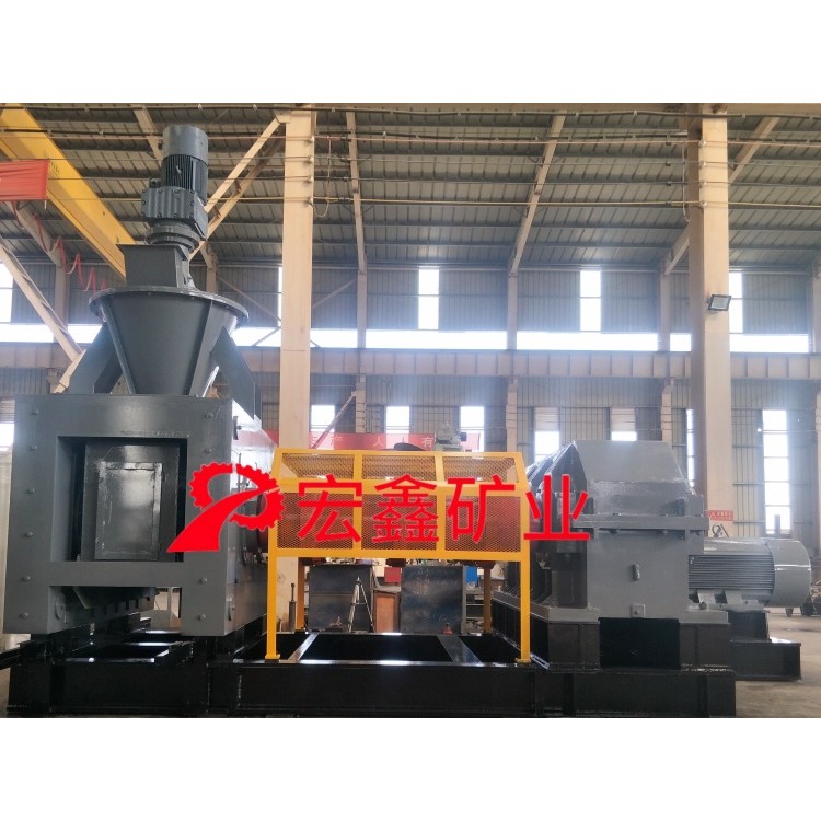
At the time of production, the ball press machine mainly consists of the following components:
1) The main body of the ball press machine. The main body includes the main frame and the hydraulic section, with an electric motor and a turbine reducer mounted on top. If the height exceeds during transportation, the press machine and the turbine reducer can be disassembled separately.
2) One main drive reducer, with a belt wheel on the input shaft and a coupling on the output shaft.
One main motor and one belt pulley included.
4) One ball press operating control cabinet and one speed indicator gauge.
One vibration separator machine (including vibration motor).
6) Attachments: Pins, V-belts, etc.
After the customer places an order, follow the instructions manual and construct the foundation according to the customer's self-designed configuration diagram (the relative elevations of the components of the ball press are determined according to this manual). Pre-drill the foundation for the anchor bolts (the installation dimensions of the anchor bolt holes are as per the manual).
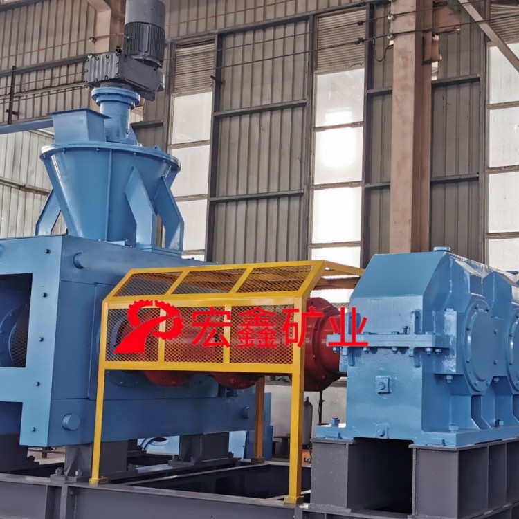
After the ball press arrives at the factory, installation should prioritize the ball press. First, roughly locate the height and level, and fasten the base bolts. Then, use the main reducer as a reference to roughly locate the height above the horizontal plane and fasten the base bolts. The main motor and main reducer are connected by a V-belt. Therefore, it is only necessary to ensure that the motor shaft and the reducer input shaft are at the same level, with the distance measured by the belt. After completing these tasks, perform secondary grouting to secure the base bolts. Washers can be used to adjust minor installation height errors. Once fine-tuning is complete, use cement to level the foundation surface, which must be done after the base bolts are tightened. The remaining components can be installed according to the assembly drawing.
2. Adjustments
The machine has been adjusted before shipment, but adjustments are still required due to issues that may arise from on-site maintenance or operation.
Production Gap Adjustment for Rollers: When increasing production output or the bite angle is necessary during production, simply increase the gap between the two rollers. Insert a thin sheet of 0.1-1mm between the active and passive bearing seats. The steps are as follows: shut down the machine, unload the oil pump, move the movable passive bearing seat towards the oil cylinder, and insert sheets of equal thickness at both ends.
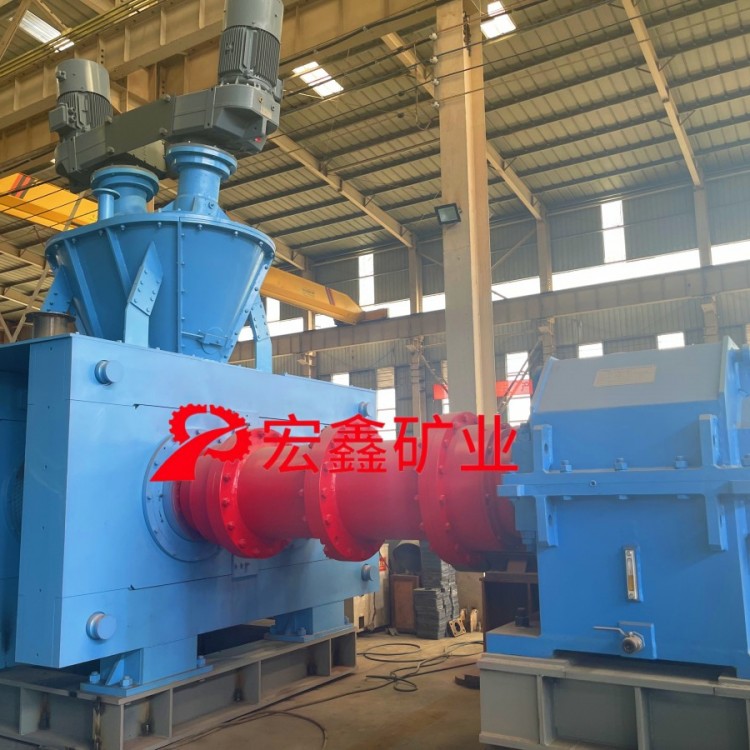
2. Ball Socket Alignment Adjustment: The ball socket is formed by the matching of concave sockets on the main and driven roller surfaces, thus presenting issues of axial alignment and circumferential alignment.
The axial alignment is pre-set during installation and generally requires minimal adjustment. When adjustment is necessary, simply tighten the bolts on the bearing cover to achieve the desired axial alignment.
B. The circumferential alignment steps are as follows: First, loosen the 4 bolts on the shaft head disk, then loosen the 11 M20 connecting screws on the adjustment sleeve. Adjusting the M20*70 bolt on the adjustment pin will achieve the purpose of circumferential alignment. If it cannot be adjusted, manually rotate the belt wheel on the main reducer to correct the misalignment, as an adjustment allowance for a ball socket has already been considered. Therefore, it can be adjusted regardless of the degree of misalignment.
Contact us

Service Hotline
13703990669
Company Telephone
13623818504

Address
Henan Province, Zhengzhou City, Longgang Economic Development Zone, Yiyang City
b2b.china9.net © Zhongshang 114 Hebei Network Technology Co., Ltd.Address: Room 6009, Oriental New World Center, No.118 East Zhongshan Road, Qiaoxi District, Shijiazhuang City, Hebei ProvincePlatform Service Hotline: 4006299930