


- AllProduct Category
-
Hydraulic Component Assembly and Disassembly Station
Engineering Hydraulic Training Expansion Bench
Hydraulic & Pneumatic Combined Test Bench
Pneumatic Test Bench
Hydraulic Test Bench


详情描述
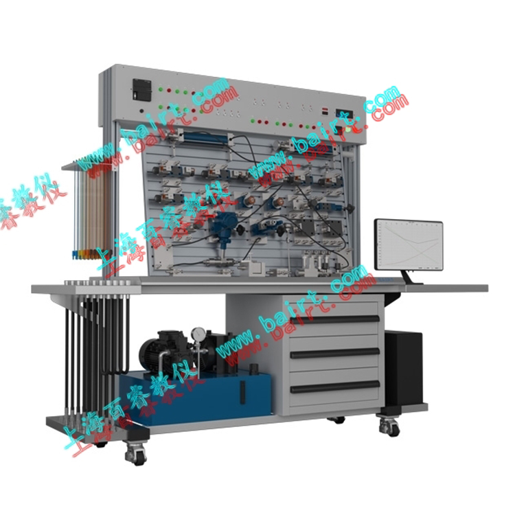
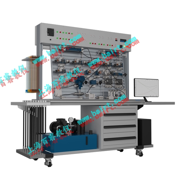
YD-C Type Electro-Hydraulic Proportional Hydraulic Test Bench


The YD-C Type Electro-Hydraulic Proportional Hydraulic Test Bench is an upgrade from the YD-B Type Intelligent Hydraulic Comprehensive Test Bench, incorporating proportional overflow valves, proportional speed control valves, and proportional directional valves, among other electro-hydraulic proportional components. It is also equipped with the corresponding data acquisition software. Utilizing advanced Rexroth hydraulic components and a unique modular design, it forms an easily assembled system, meeting the educational needs of colleges and universities for proportional control experiments in hydraulic control. It aims to cultivate students' hands-on skills, design abilities, and comprehensive application capabilities, enhancing their innovative design skills.
I. Lab Bench Main Structure: An introduction to the main components of this lab bench, which has undergone a complete redesign in 2021: Featuring a novel, stylish, and tech-attractive theme, supported by the aesthetics of strength, guided by the golden ratio, inspired by visually pleasing color schemes, with a focus on convenience and safety, aiming for multi-functional practicality. The latest design results in a sturdy and durable bench, with easy storage and retrieval of components, enhanced functionality of the work surface, and a great visual impact of technology and fashion.
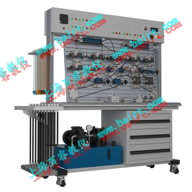
1. Lab Workbench (Innovative Feature)
1.1 The columns on both sides of the experimental table are made of industrial-grade aluminum-magnesium alloy profiles, ensuring sufficient support strength while maximizing lightweight design. The column dimensions are 100*50*1100*2mm, with anodized surface treatment to form a thick and dense oxide film layer on the surface, significantly improving the corrosion resistance, hardness, wear resistance, and silver gray metallic texture of the column. The column slots are fitted with custom-made ultra-light (30g/m) U-shaped槽 strips with a thickness of 10*8.6*6.4mm*0.9mm, custom RAL5017 color, complementing the silver gray columns and greatly enhancing the product's appearance and the overall technological feel of the laboratory.
1.2 The two X-shaped support structures on the underside of the experimental table, inspired by the same-named science fiction movie "X-Men," give the product a sci-fi vibe. The welding material is rectangular steel 100*50*2 (mm), which is made after cutting, welding, sanding, and spraying with non-formaldehyde, non-phosphorus 9003, followed by a 200° high-temperature baking process (powder detection report required); the surface features a silk-screened company's exclusive English registered trademark BAIRT, in a sci-tech blue color, complementing the column decorative strips; the angle of the X-shaped support structure is 62 degrees, with the X-shaped intersection approximately 448mm from the ground. Additionally, the silk-screened trademark BAIRT's letter T is precisely located at the X-shaped intersection, positioning the silk-screened trademark BAIRT at the overall golden section point (0.618 ratio) of the X-shaped support structure, providing an extremely comfortable visual experience.
1.3 Optional sliding built-in hose storage rack on the lab table, a design innovation in the industry, integrating hose storage, dust prevention, and space-saving into a single design philosophy. It can slide smoothly along the longitudinal direction of the lab table. Maximizing the use of the limited storage space on the lab table, it optimizes the convenience of hose retrieval to the fullest. The sliding built-in hose storage rack can stop and lock at any position, relying on professional custom-molded industrial sliding guides. The sliding travel is 500mm (can be customized up to 600mm), and the dimensions of the hose storage rack are: 510*180*30 (mm), with a groove width of 23 millimeters; it can support a load of 20.5 kilograms and can store nearly 40 hoses.
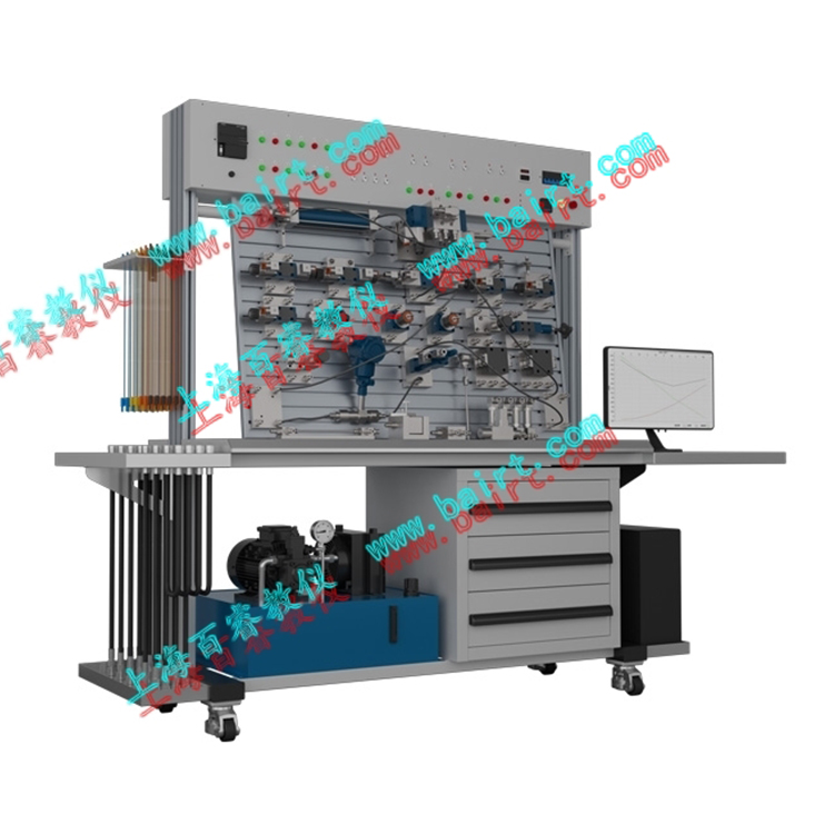
1.4 The central aluminum alloy experiment panel of the laboratory table features a floating adjustable design. By incorporating a rotating O-point at the top rear of the panel, the experiment panel can be tilted from 0-90° to meet teaching requirements. The appropriate tilt of the panel offers significant advantages in teaching, providing the experimenter with a more comfortable operating angle. It can be adjusted to a horizontal angle parallel to the ground, achieving the functionality of a horizontal experiment table, catering to the comfort of human-machine interaction. The experiment panel is composed of 16 strips of aluminum extrusions, each custom-molded for specific use, measuring 1200*732*18mm. The aluminum extrusions are skillfully constructed, featuring locking grooves for a unified whole upon assembly. The front of the aluminum extrusions features a T-slot design for easy placement and installation of experimental components. The surface of the aluminum extrusions is also anodized to enhance corrosion resistance, hardness, wear resistance, and achieve a silver gray premium metal texture, resulting in an aesthetically pleasing and grand overall appearance.
The central work surface of the lab table is made of reinforced wood structure and is covered with an oil-resistant and easy-to-clean transparent crystal pad (thickness: 3mm). The moderate thickness effectively prevents accidental dropping of components during experiments from damaging the table surface. Additionally, the oil-resistant and easy-to-clean PVC pad has a smooth surface, which can be easily cleaned by simply wiping with a cloth.
1.6 The storage cabinet on the underside of the lab table is made of industrial-standard full steel body, measuring 450*390*520mm, with 1mm thick sheet metal. It is coated with 9003 powder without formaldehyde and phosphorus, baked at a high temperature of 200°, resulting in a smooth surface. It features a three-layer pull-out structure, ample internal space, comes with a lock for easy item storage, and includes two spare keys. The keys are 800 different designs, ensuring they do not open each other, enhancing security.
1.7 This lab bench features an extended protection function, controlling high salt, high humidity, and dampness environments. It purifies the lab atmosphere, enhancing the equipment's operating environment, extending its lifespan, and improving the comfort of the operators. Suitable for lab spaces of approximately 100M2 per bench, operating voltage: 220V/380V, control mode: APP intelligent remote control or manual, noise level below 30dB, with timing and delay functions.
1.8 Workbench Size: Length x Width x Height = 2300mm x 650mm x 1800mm. Gross/Net Weight (KG): 450/385KG
Section II: Product Introduction
1. Hydraulic Pump Station System Rated Working Pressure: 6.3 Mpa (up to a maximum of 7 Mpa).
1.1 Electric Motor-Pump Unit (1 unit) - Motor: Three-phase AC voltage, power 1.5Kw, speed 1450r/min. Variable Vane Pump: Single direction, nominal displacement 6.67mL/r, volumetric efficiency 90%.
1.2 Nominal fuel tank capacity: 40L; equipped with liquid level and oil temperature gauges, oil and return oil filters, safety valve, etc.
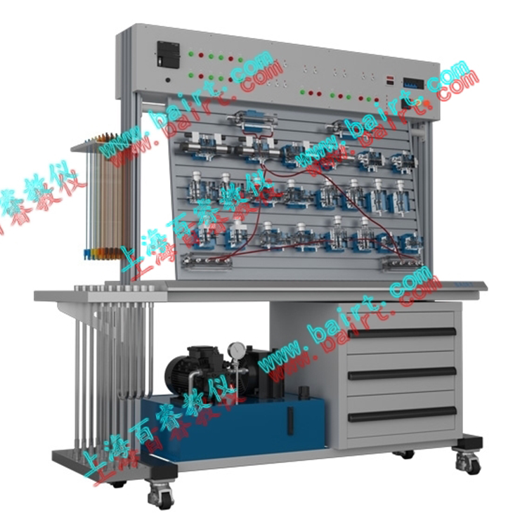
2. Common hydraulic components are primarily from Beijing Huade Hydraulic Components, with configurations detailed in the configuration list. Each hydraulic component comes with an oil path transition base, allowing for easy and flexible placement on aluminum alloy panels.
3. The electrical measurement and control unit features an optional split modular structure, with each module serving an independent function. During experiments, modules can be freely selected as needed. Common modules include: power module, pump control module, relay module, button module, PLC module, etc. Standard product configuration: Siemens S7-200, SMART series, SR20, relay output. Customers can choose the PLC brand they need according to their specific requirements.
4. The data procurement unit employs a renowned domestic testing and analysis system, measuring flow, pressure, power, RPM, time, and temperature -- computer human-machine interface -- computerized intelligent data collection, analysis, and processing -- automatic generation of production reports, curves, and a series of automated actions, ultimately completing the hydraulic test. This testing bench is a professionally designed new-generation intelligent hydraulic transmission testing bench and serves as an example of full automation in hydraulic testing.
5. Lab Bench Function
5.1 Performance Testing of Common Hydraulic Components:
Hydraulic Pump Performance Testing (Static, Dynamic)
2) Overflow Valve Performance Testing (Static, Dynamic)
3) Throttle Valve and Flow Control Valve Performance Testing
4) Pressure Relief Valve Performance Testing (Static, Dynamic)
5) Damping Hole Performance Test (Optional)
5.2. Basic Hydraulic Transmission Circuit Experiments: (45 types of circuits) Direction Control Circuit, Manual Directional Change Valve Circuit, Three-Way Four-Port Solenoid Directional Change Valve Circuit, Two-Way Four-Port Solenoid Directional Change Valve Circuit, Pressure Relay-Controlled Automatic Retraction Circuit, Two-Way Four-Port Solenoid Directional Change Valve, Three-Way Directional Change Valve Circuit, Two-Way Valve Start/Stop Circuit, Three-Way Valve Start/Stop Circuit Pressure Control Circuit, Single-Stage Pressure Regulation Circuit, Two-Stage Pressure Regulation Circuit, Multi-Stage Pressure Regulation Circuit Directional Change Valve Unloading Circuit, One-Way Check Valve Back Pressure Circuit, Pressure Reducing Valve Pressure Reduction Circuit, Sequence Valve Balance Circuit, Pilot-Type Overflow Valve Unloading Circuit, Locking Circuit Using O-Type Directional Change Valve, Locking Circuit Using M-Type Directional Change Valve, Single-Direction Pressure Retention Locking Circuit for Liquid-Controlled Check Valves, Double-Direction Pressure Retention Locking Circuit for Liquid-Controlled Check Valves, Stable Pressure Circuit for Isolating Pressure Fluctuations, Pressure Retention Circuit for Liquid-Controlled Check Valves, Overflow Valve Buffer Circuit, Double-Direction Pressure Adjustment Circuit, Two-Way Valve Unloading Circuit, Speed Control Circuit Throttle Valve Inlet Throttle Speed Regulation Circuit, (One-Way) Throttle Valve Return Throttle Speed Regulation Circuit, (One-Way) Throttle Valve Bypass Throttle Speed Regulation Circuit, (One-Way) Throttle Valve Inlet Throttle Speed Regulation Circuit, (Double-Way) Throttle Valve Return Throttle Speed Regulation Circuit, (Double-Way) Throttle Valve Bypass Throttle Speed Regulation Circuit, (Double-Way) Throttle Valve Short-Circuit Speed Transfer Circuit, Throttle Valve Short-Circuit Speed Transfer Circuit, Unidirectional Throttle Valve Control, Synchronous Circuit, Unidirectional Throttle Valve Synchronous Circuit, Differential Circuit Throttle Valve Double-Direction Synchronous Circuit, Sequential Action Circuit Proximity Switch-Controlled Sequential Action Circuit, Sequence Valve-Controlled Sequential Action Circuit, Pressure Relay-Controlled Sequential Action Circuit
5.3 Proportional Hydraulic Related Experiments
5.3.1 Proportional Spill Valve Experimental Project:
I. Static Characteristics
1. Stable Pressure Control Characteristics
2. Steady-state Load Characteristics (Pressure-Flow Characteristics)
3. Pressure offset and pressure swing (pressure deviation and pressure vibration)
II. Dynamic Characteristics (Electrical feedback, valve core position signal as output signal)
1. Frequency Response (Frequency Domain Characteristics)
2. Transient Response (Step Response of Input Signal) (Time Domain Characteristics)
3. Load Flow Step Response Characteristics (Hydraulic Pump Experiment Required)
5.3.2 Proportional Throttle Valve Experimental Project
I. Static Characteristics
1. Steady Flow Control Feature
2. Steady-state load characteristics (pressure-flow characteristics)
II. Dynamic Characteristics (Electrical Feedback, Valve Core Position Signal as Output Signal)
Frequency Response (Frequency Domain Characteristics)
2. Transient Response (Step Response of Input Signal) (Time Domain Characteristics)
5.3.3 Proportional Directional Control Valve Test Item:
I. Static Characteristics
Steady-state flow control characteristics under constant valve pressure drop
2. Load Flow Characteristics (Output Flow - Load Pressure Difference PL (PA-PB/P1-p2) Characteristics)
3. Flow Rate — Valve Pressure Drop (PS-PL) Characteristic 4. Pressure vs. Input Signal Characteristic (Pressure Gain Characteristic)
Section II: Dynamic Characteristics (Electrical feedback, valve core position signal as output signal)
Frequency Response (Frequency Domain Characteristics)
2. Transient Response (Step Response of Input Signal) (Time Domain Characteristics)
Section 3: Valve-controlled Cylinder Position Closed-loop Experiment
4. Valve-controlled Cylinder Pressure Closed-loop Test
V. Valve-controlled Cylinder Frequency Vibration Test
Six, Valve-controlled Motor Speed Closed-loop Test (Optional)
5.4. Programmable Logic Controller (PLC) Electrical Control Experiment, Integrated Mechanical-Electrical-Hydraulic Control Experiment Format.
1) Learning PLC instruction programming and ladder diagram programming
2) Learning and Utilization of PLC Programming Software
3) Communication between PLC and computer, online debugging and monitoring
4) Optimization of PLC control for hydraulic transmission
5.5. Excavator Simulation Kit (Optional accessory)
1) Observation, disassembly, and analysis of the structural components of hydraulic transmission and study of the principles of hydraulic control systems.
2)Hydraulic Excavator Demonstration Control Experiment
Excavation operations, involving combined bucket and dipper rod working tests.
② The unloading operation, boom, and bucket work simultaneously, with the large arm capable of adjusting its position and height.
5.6. Loader Simulation Unit (Optional accessory)
1)Observation of hydraulic transmission component structures, disassembly, and analysis of the principles of hydraulic control systems.
2)Hydraulic Loading Machinery Demonstration Control Experiment
①Loading operation, after the bucket is filled, the arm cylinder extends to reverse the bucket, lifting the boom arm.
② Unloading operation, bucket unloading (retracting the boom to turn the bucket), and lowering the arm.
5.7. Student-designed and assembled expandable hydraulic circuit experiments; (over a hundred experiments can be expanded)
6. Programmable Logic Controller (PLC) electrical control experiment, integrated mechanical, electrical, and hydraulic control experiment format.
1)PLC instruction programming, ladder diagram programming study
2)PLC Programming Software Learning and Usage
3)PLC communication with computer, online debugging and monitoring
4)Optimization of PLC control for hydraulic transmission
询价单


