


- AllProduct Category
-
Hydraulic Component Assembly and Disassembly Station
Engineering Hydraulic Training Expansion Bench
Hydraulic & Pneumatic Combined Test Bench
Pneumatic Test Bench
Hydraulic Test Bench


详情描述
YD-B Model Intelligent Hydraulic Transmission Test Bench


Overview:
YD-B Type Intelligent Hydraulic Transmission Comprehensive Experimental Bench is based on "Hydraulic Transmission"HydraulicIn accordance with the requirements of textbooks like "Pneumatic Transmission," and based on suggestions from educators and students, we have meticulously designed this. The experimental bench utilizes advanced hydraulic component technology and innovative modular design, allowing hydraulic components to be easily and quickly mounted on the T-slot aluminum alloy panel. Coupled with the advanced self-sealing quick connector, it forms a convenient and easy-to-assemble system.
The YD-B Intelligent Hydraulic Transmission Comprehensive Experimental Bench is an upgrade from the YD-A model, featuring additional sensors, data acquisition cards, and test software. By measuring parameters such as pressure, temperature, power, flow rate, speed, and time through the data acquisition card, and with the analysis and processing capabilities of the test analysis software, data can be saved, curves can be plotted, and experimental reports can be exported. This enables efficient conduct of relevant experimental courses in the hydraulic transmission curriculum.
The YD-B Type Intelligent Hydraulic Transmission Comprehensive Experimental Bench is suitable for teaching experiments in courses such as "Hydraulic and Pneumatic Transmission" and "Principles and Applications of PLC Programmable Logic Controllers" in mechanical engineering, mechatronics, and automation programs at colleges and universities, technical schools, and vocational schools. It can also serve as a comprehensive experimental bench for mechanical, electrical, and hydraulic integration. Students can accurately, vividly, and deeply understand and master the structure of hydraulic components, the control principles and design methods of hydraulic circuits, and other aspects through practical operation experiments and course design. They can also grasp the functions, control principles, and programming techniques of PLC programmable controllers.
This experimental bench is a newly designed professional intelligent hydraulic transmission bench, a model of full automation in hydraulic experiments.
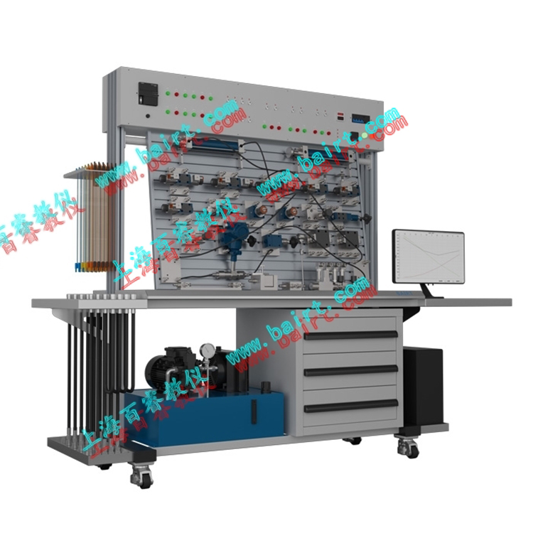
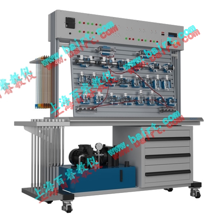
I. Lab Bench Composition
The laboratory bench is composed of several parts, including the experimental workbench, hydraulic pump station, common hydraulic components, electrical control unit, and data acquisition system.
1. Laboratory Workbench
Power Supply: 3-phase 4-wire 380V, Rated Power: 1.5KW, Rated Pressure: 6.3-7Mpa
The lab workbench is composed of an iron frame, electrical cabinet, oil pipe rack, computer desk, and aluminum alloy profile panels (T-slot).
Manufactured from high-quality 2mm Baosteel cold-rolled steel plate; aesthetically pleasing and sturdy, equipped with four premium swivel casters for easy movement. The cabinet is divided into two sections below: the left side for placing the pump station; the right side serves as a storage cabinet for hydraulic components.
The experimental workbench is composed of a main body made of iron (formed by a single molding process) and an aluminum alloy profile operating panel. The panel features an aluminum alloy profile structure with "T" groove, allowing for convenient and flexible installation of hydraulic components and connection of experimental circuits.
Workbench dimensions: L×W×H=1500mm×650mm×1800mm (Approx. 300kg after packaging)
Computer desk attachment: Length x Width x Height = 500mm x 650mm (Approx. 10kg after packaging)
2. Hydraulic Pump Station
System rated working pressure: 6.3 Mpa (up to a maximum of 7 Mpa).
Electric motor-pump assembly (1 unit)
Variable impeller pump - Motor 1 unit
Variable Vane Pump: Single-direction, nominal displacement 6.67 mL/r, volumetric efficiency 90%.
Motor: 3-phase AC voltage, 2HP 4P, 1450r/min speed
⑵. Fuel Tank: Nominal Capacity 45L; equipped with liquid level and oil temperature gauge, oil and filter, air filter, etc.
3. Common Hydraulic Components
Hydraulic components primarily produced by Beijing Huade Group, configuration details are listed in the configuration sheet.
Each hydraulic component comes with an oil path transition base, allowing for easy and convenient placement on the aluminum alloy profile panel.
4. Electrical Measurement and Control Unit
Programmable Logic Controller (PLC): Siemens S7-200 series, 20 I/O points, relay output, power voltage: AC 220V/50Hz, control voltage: DC 24V, equipped with manual, automatic, timing, and sequential control functions, along with pressure gauges, flow meters, power meters, speedometers, and timers for measurement.
Standard configuration brands are recommended by our company, while customers can also select the required PLC brands based on their own needs.
5. Data Collection System
Computer: PIV processor, 19-inch LCD monitor, operating system Microsoft Win7 or higher, screen resolution 1600*900 or higher
Data Analysis Software: Hydraulic Drive Test Analysis System V1.0
Data Acquisition Card - 12-Channel, 16-bit High-Precision Analog Signal Acquisition
Pressure Transmitter, Flow Transmitter, Power Transmitter, Temperature Transmitter, Displacement Transmitter O.5 Accuracy Level
II. Lab Bench Functionality
Performance Testing of Common Hydraulic Components
1) Hydraulic Pump Performance Testing
2) Static performance test of overflow valve
3) Throttle Valve and Flow Control Valve Performance Testing
4) Pressure Relief Valve Performance Testing
5) Damping Hole Performance Test (Optional)
2. Basic Hydraulic Transmission Circuit Experiments: (22 circuits)
1) Single Stage Pressure Reducing Loop
2) Two-stage pressure regulating circuit
3) Pressure Relief Valve's Pressure Reduction Circuit
4) Sequence Valve Balance Loop
5) Directional valve's unload circuit
6) Lead-type Pressure Relief Valve's Dumping Circuit
7) Pressure-holding and self-locking circuit for hydraulic check valves
8) Differential Circuit
9) Speed Control Valve Short-Circuiting Speed Transfer Loop
10) Throttle Valve Feed Flow Control and Speed Regulation Circuit
11) Throttle valve return flow throttling speed control circuit
12) Throttle Valve Bypass Throttle Control Loop
13) Throttle Valve Feed Flow Control Loop
14) Throttle valve return flow throttle control loop
15) Flow Control Bypass Throttle Speed Control Loop
16) Throttling valve-controlled unidirectional synchronous loop
17) Double Four-way Electromagnetic Directional Valve Reversing Circuit
18) Three-way four-way solenoid directional valve directional circuit
19) Two-way four-way manual directional valve reversing circuit
20) Sequential Action Circuit Controlled by Sequential Valve
21) Sequence action circuit controlled by proximity switch
22) Sequence action circuit controlled by pressure relay
3. Programmable Logic Controller (PLC) electrical control experiment, integrated mechanical, electrical, and hydraulic control experiment format.
1) Learning PLC instruction programming and ladder diagram programming
2) Learning and Using PLC Programming Software
3) Communication between PLC and computer, online debugging and monitoring
4) Optimization of PLC control for hydraulic transmission
4. Excavator Simulation Unit (optional accessory)
1) Observation of hydraulic transmission component structures, disassembly and assembly, as well as study and analysis of the principles of hydraulic control systems.
2) Hydraulic Excavator Demonstration and Control Experiment.
Excavation operations, bucket and dipper rod working in combination for experimental purposes.
②Material discharge operation, bucket arm and bucket function simultaneously, with the large arm adjustable for height positioning.
5. Loader Simulation Unit (Optional accessory)
1) Observation of hydraulic transmission component structures, disassembly and assembly, and study and analysis of the principles of hydraulic control systems.
2) Hydraulic Loading Machinery Demonstration and Control Experiment.
①Material loading operation: After the bucket is loaded, the arm cylinder extends, causing the bucket to reverse and the boom to lift.
② Discharging operation, bucket unloading (retracting the boom to turn the bucket), the arm descending.
6. Self-designed and assembled hydraulic circuit experiments by students; (expandable to over a hundred experiments)
7. Programmable Logic Controller (PLC) electrical control experiments, integrated mechanical, electrical, and hydraulic control experiment format.
1) Learning of PLC instruction programming, ladder diagram programming
2) Learning and using PLC programming software
3) Communication between PLC and computer, online debugging and monitoring
4) Optimization of PLC control for hydraulic transmission
8. Intelligent Data Collection System Experiment: Capable of experimental data collection, analysis, processing, real-time display, and automatic generation of experimental curves.
9. Equipped with simulation software, capable of simulating the connection of a hydraulic test circuit.
Virtual hydraulic configuration simulation software:
This configuration software can graphically and in real-time display the flow direction of hydraulic oil, the operating status of various hydraulic valve cores, the working process of the cylinders, and the working principle of the pump on the computer screen.
10. Add hydraulic simulation software with features for virtual circuit connection and fault detection.
询价单


