


- AllProduct Category
-
Hydraulic Component Assembly and Disassembly Station
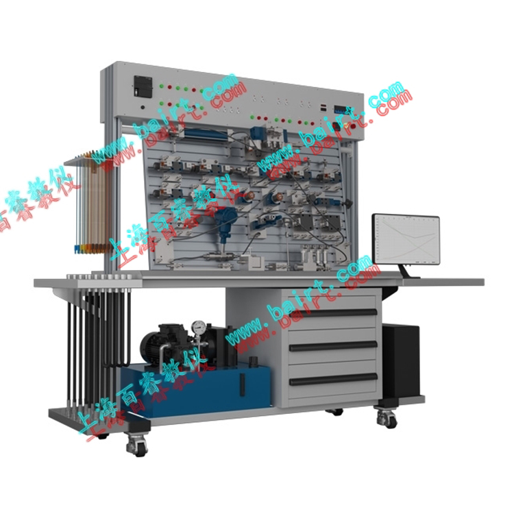
Engineering Hydraulic Training Expansion Bench
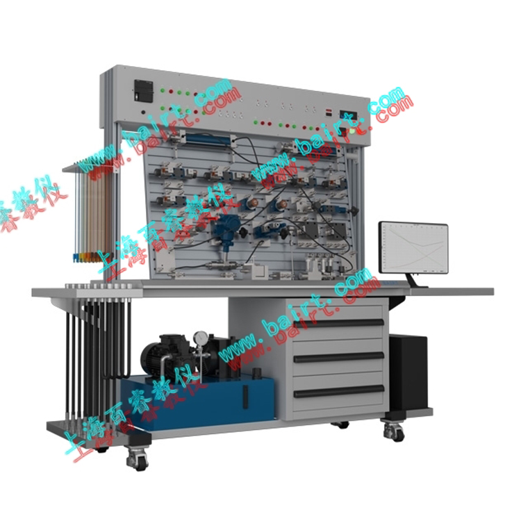
Hydraulic & Pneumatic Combined Test Bench
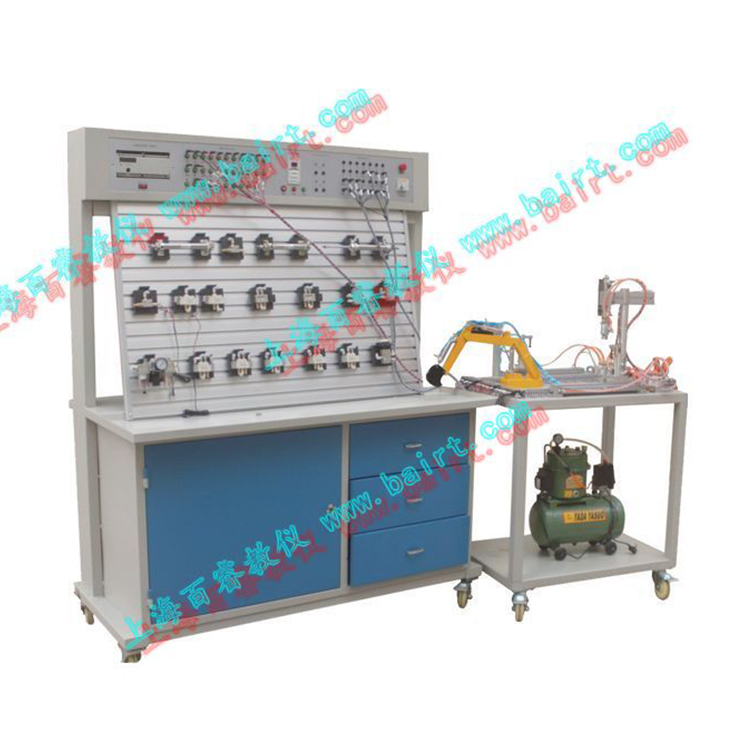
Pneumatic Test Bench
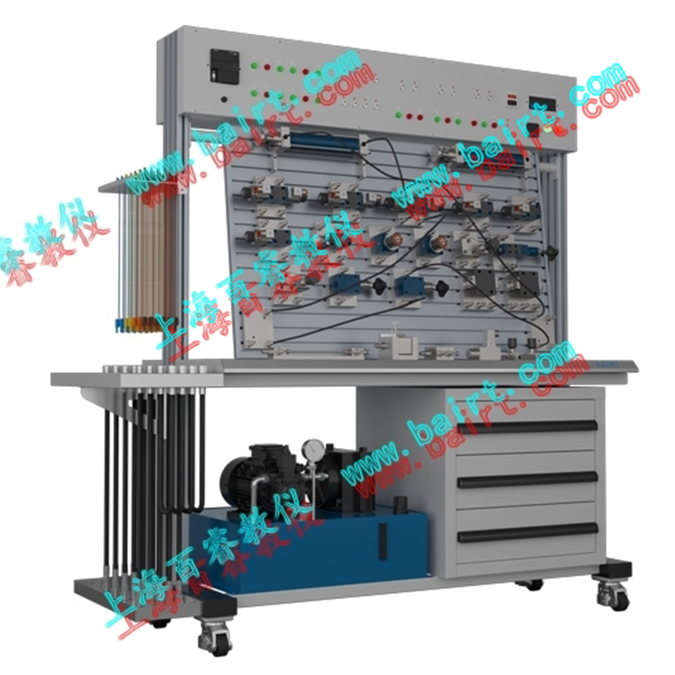
Hydraulic Test Bench


详情描述

Overview:
The experimental bench is designed based on general textbooks such as "Hydraulic and Pneumatic Transmission Technology and Practice" and "Pneumatic Control Technology." It integrates programmable logic controllers (PLCs) and industrial pneumatic components and execution modules. In addition to conducting routine pneumatic basic control circuit experiments, it also allows for the design and implementation of pneumatic-electrical control circuit applications and pneumatic-PLC control circuits, covering various pneumatic technology courses.
I. Key Features:
1. Component Modularization: Each pneumatic component is an independent module, equipped with an easy-to-install base plate. It can be freely assembled on universal aluminum alloy profiles to form various experimental circuits, with simple and quick operation.
2. Connection Method: The joints feature quick coupling, ensuring reliable and easy installation and disassembly, saving time.
3. Pneumatic Components: Standard industrial pneumatic components, reliable and safe in performance.
4. System Environment: Low-noise work station, providing a quiet experimental environment (noise < 60 dB).
Section II: Available Practical Training Projects(Subject to the specific terminal execution structure selected)
1. Assembly and testing of the basic gas circuit.
Students can construct experimental circuits based on the circuit diagram and conduct relevant experiments.
2. Training on the installation and debugging of the pneumatic loader simulation unit.
3. Training on the installation and debugging of the pneumatic excavator simulation unit.
4. Installation and debugging training for a small logistics handling station simulation facility.
5. Training on the installation and debugging of a modular flexible automation production training system.
6. Sensor Application Technology Training
The sensors involved in the device include capacitive, inductive, photoelectric, and electromagnetic types, each with its own characteristics and different functions, ensuring the system operates reliably. Students can enhance their intuitive understanding of these sensors by studying the working characteristics of various sensors in use, allowing them to quickly master the knowledge acquired.
7. Pneumatic Application Technology Training
The pneumatic components involved in the installation include: electrically controlled pneumatic valves, various pneumatic cylinders, pneumatic grippers, vacuum suction cups, vacuum generators, filter-reducing valves, etc. When studying these pneumatic components, not only can each individual component be studied separately, but also the coordination and operation of various pneumatic components with each other, as well as with other components, can be understood during the learning process.
8. PLC Programming Training
Students can not only learn various PLC technologies on this equipment, but also study multiple applications of PLCs in an integrated technological environment. It provides the conditions for flexible learning and mastering all aspects of PLC knowledge.
9. Electrical Control Circuit Training
The electrical control part of the equipment is designed in accordance with industrial standards and conventions, and design drawings and manuals are provided. Students can learn circuit diagram analysis, PLC I/O address checking, and equipment circuit wiring methods on this equipment.
10. Mechanical System Debugging Training
During online debugging, students must adjust the coordination between units to ensure the system operates normally and reliably. This greatly helps improve the practical skills of the students on campus.
11. System Maintenance and Fault Detection Technical Training
Daily maintenance content and methods for equipment, as well as common system fault analysis and troubleshooting methods.
Pneumatic Basic Circuit Experiment Projects:
PLC Control Loop Experiment
Interlocked circuit
2. Buffer Loop
3. A single pressure control loop
4. Secondary Pressure Control Loop
5. Speed Transfer Loop
6. Double-acting cylinder bidirectional speed control circuit (inlet and outlet adjustment)
7. High/Low Pressure Switching Circuit
8. Double-acting cylinder reversing circuit
9. Single-acting cylinder directional circuit
10. Overload Protection Circuit
11. Time-controlled single reciprocating loop
12. Pressure Control Single Reciprocating Loop
13. Position Control Single Back-and-Forth Loop
14. Continuous reciprocating action circuit for single and double-acting cylinders
15. Throttling Valve-Synchronized Circuit
16. Three-cylinder Linked Circuit
17. Counting Loop
18. Delayed Loop
19. OR logic application circuit (OR AND logic)
20. Hand-Operated Loop
Programmable Logic Controller (PLC) Electrical Control Experiment, Mechanical-Electrical-Pneumatic Integrated Control Experiment:
PLC Basic Instruction Programming, Special Instruction Programming, Ladder Diagram Programming Learning
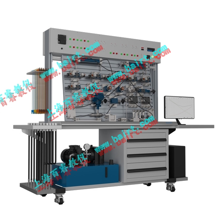
(2) Learning and Usage of PLC Programming Software
PLC communication with computers, online debugging
PLC and Pneumatic Combined Control Experiment
③ Students can independently design, assemble, and expand over 130 types of circuit experiments
④ Extensibility Innovation Experiment
This experimental bench is equipped with internationally advanced Japanese SMC pneumatic valves, a high-configured Omron 60-point programmable controller, and the leading FESTO simulation software, forming this domestic experimental platform. We did not create a fixed and unchanging verification platform for this equipment; instead, we provide a comprehensive, safe, and open innovation operation platform. Under the guidance of teachers, it truly realizes the transformation from verification experiments to innovative experiments, and from passive experiments to active experiments.
To accommodate the requirements of school experimental teaching reform, reduce confirmatory experiments, and increase design-oriented, comprehensive, and exploratory experiments, fostering students' independent innovative thinking. In addition to completing fundamental experiments on air pressure, it should be integrated with mechanical experimental projects to achieve the effect of one machine with multiple functions; such as:
Excavator Simulator Mechanism
Revolving feeding mechanism
360-degree rotating robotic arm
Automated small-scale logistics transportation line
Interfaced with Festo Germany software, capable of simulating various mechanical applications.
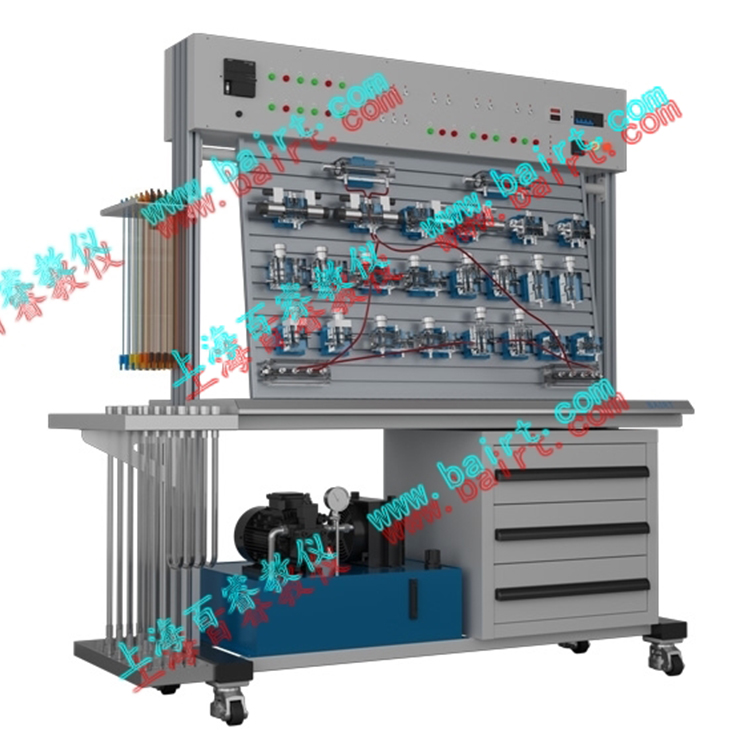
Section 3: Laboratory Table Composition:
The lab bench is composed of several parts, including the bench frame, work pump station, pneumatic components, electrical control unit, and auxiliary parts.
1. Lab BenchThe lab bench frame is constructed from a single-cast iron body (steel plate over 1.0mm thick) and an aluminum alloy operating panel, featuring a leak-proof return oil groove for practicality. The entire frame undergoes rust and oil removal, sandblasting, and powder coating processes, followed by rust, dust, and static electricity protection treatments, ensuring safety and reliability.
Workbench
Main Dimensions: Length x Width x Height = 1500mm x 650mm x 1700mm (Gross Weight Approx. 250kg)
Dimensions: Length x Width x Height = 1000mm x 650mm x 800mm (Gross Weight Approx. 150kg)
2. Work Pump Station:
Air Pump Input Voltage: AC 220V/50HzMotor (Dual Head) Power: 250WRated Output Pressure: 0.8 MpaAir Pump Volume: 20L
Work noise: < 60 decibels
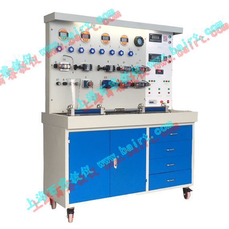
3. Pneumatic Components:
Japan-origin imported components, primarily SMC pneumatic components, configuration details are in the attachment.
All pneumatic components are equipped with a sky blue transition base (fiberglass ABS), allowing for easy and flexible placement on the experimental panel (constructed with an aluminum alloy profile in the form of a "T" groove). The circuit junctions use quick-release connectors, ensuring convenient and fast assembly and disassembly, as well as safety and reliability under low pressure.
4. Electrical Control Unit:
Programmable Logic Controller (PLC); Omron brand from Japan, 60 I/O points; relay output type.
Power Voltage: AC 220V/50Hz
5. A set of German FESTO pneumatic simulation software.
询价单


