


- AllProduct Category
-
Hydraulic Component Assembly and Disassembly Station
Engineering Hydraulic Training Expansion Bench
Hydraulic & Pneumatic Combined Test Bench
Pneumatic Test Bench
Hydraulic Test Bench


详情描述
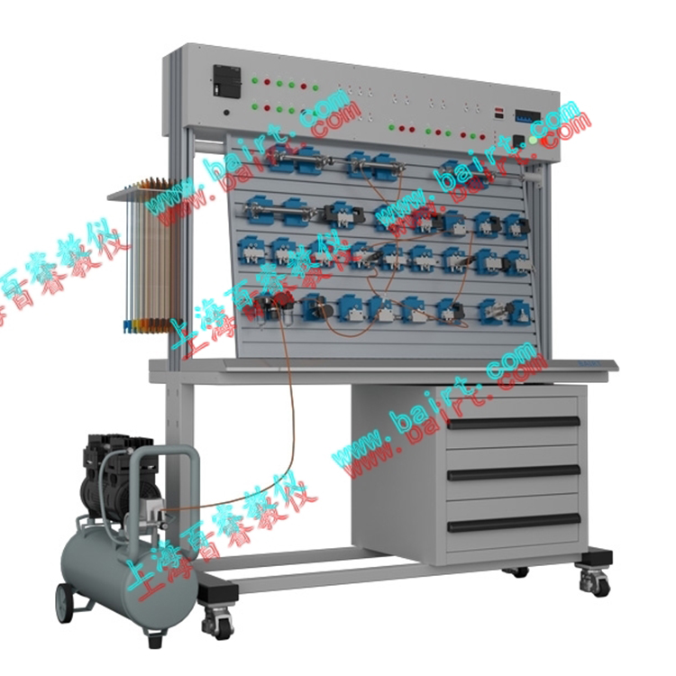
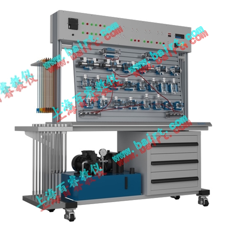
QD-B Type Double-Sided Pneumatic Test Bench


Compared to the QD-A model, the workbench of the QD-B model features a dual-sided design: a single experimental workbench is equipped with two sets of pneumatic components, sharing a single work pump source. This allows two groups of students to conduct independent experiments simultaneously on a single workbench, fully utilizing the existing experimental equipment and achieving resource sharing! It is fully equipped with all the functions of the QD-A model. Its performance-to-price ratio is nearly doubled! The specific structural and performance features are as follows:
Similarly, the QD-B type pneumatic PLC control integrated teaching and experimental set is designed to meet the requirements of modern pneumatic professional teaching and experiments. Based on the contents of general textbooks such as "Hydraulic and Pneumatic Transmission" and "Pneumatic Control Technology," this system is designed. In addition to conducting conventional pneumatic basic control circuit experiments, it can also perform simulation experiments on the application of pneumatic control technology and pneumatic technology course design.
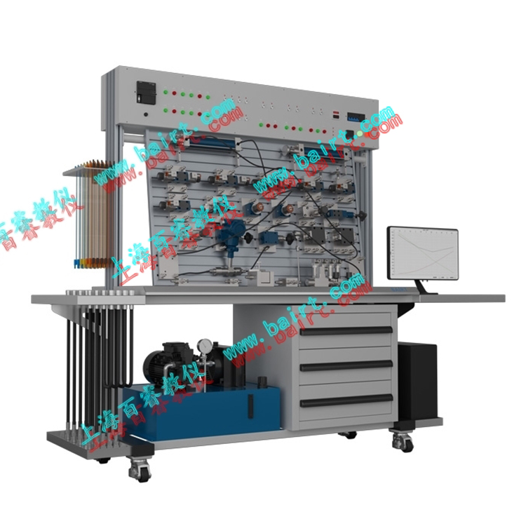
The experimental equipment adopts PLC control. It connects the PLC control system with a computer, enabling experiments from basic PLC instruction programming to ladder diagram programming, and further into the application of PLC control, including communication with computers and online debugging functions. It is a perfect integration of pneumatic technology and electrical PLC control technology.
I. Key Features:
The workbench features a double-sided structure, allowing two groups of students to conduct experiments simultaneously, offering an excellent product performance-to-price ratio.
2. Modular structure design facilitates easy and convenient assembly. Each pneumatic component is an independent module, equipped with a base plate for easy installation. During experiments, various test circuits can be assembled freely on the universal aluminum alloy profile board, offering simple and convenient operation.
3. Reliable connection joints for easy and time-saving installation.
4. Standard industrial components with reliable performance, safety, and edge.
5. Low-noise work pump station, providing a quiet experimental environment (noise < 60 dB)
II. Experimental Projects:
Loop Test
Single-acting cylinder reversing circuit
2. Double-acting cylinder reversing circuit
3. A single pressure control loop
4. Secondary Pressure Control Loop
5. High/Low Pressure Switching Circuit
6. Double-acting cylinder bidirectional speed control circuit (import adjustment, export adjustment)
7. Speed Switching Loop
8. Buffer Loop
9. Interlocked Loop
10. Overload Protection Circuit
11. Position-Controlled Single-Direction Reciprocating Loop
12. Pressure-Controlled Single Reciprocating Loop
13. Time-controlled one-way reciprocating loop
14. Continuous reciprocating circuit of single-acting and double-acting cylinders
15. Throttling Valve-Based Synchronized Loop
16. Three-cylinder Linked Circuit
17. Counting Circuit
18. Delayed circuit
19. Logic Valve Application Circuit (or Logic)
20. Manual operation circuit
Programmable Logic Controller (PLC) Electrical Control Experiment, Integrated Machine-Electricity-Pneumatic Control Experiment:
PLC programming instructions, ladder diagram programming study
(2) Learning and Using PLC Programming Software
PLC communication with computers, online debugging
PLC and Pneumatic Combined Control Experiment
③ Students independently design, assemble, and expand various circuit experiments
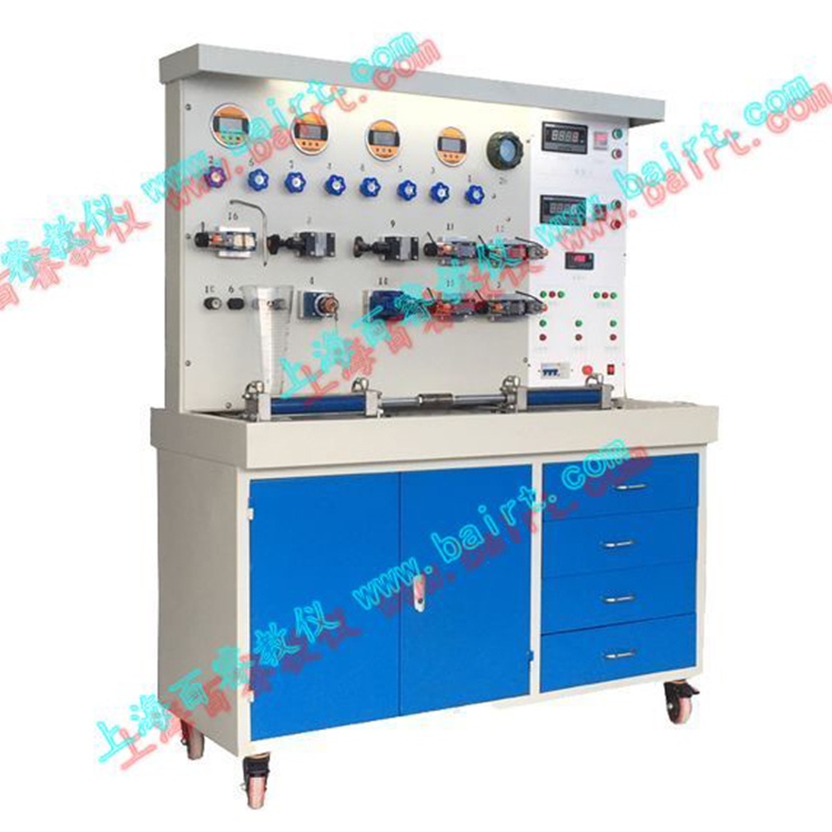
III. Lab Bench Composition:
The laboratory table consists of several parts, including the table frame, work pump station, pneumatic components, and electrical control unit.
1. Lab BenchThe laboratory bench is composed of an iron frame and an aluminum alloy operation panel.
Workbench Dimensions: Length x Width x Height = 1500mm x 750mm x 1700mm (Approx. packed weight: 300kg)
2. Work Pump Station:
Utilizing a silent air compressor to provide a better training environment for the lab.
Air Pump Input Voltage: AC 220V/50Hz Motor (Dual Head) Power: 250W
Rated Output Pressure: 0.8 Mpa Air Pump Capacity: 20LWork Noise: < 60 dB
3. Pneumatic Components
3-1) Pneumatic components are primarily JELPC pneumatic components, each being an independent module with a blue quick-installation base plate. This allows for easy and flexible placement of the components on the training panel (an aluminum alloy profile structure with "T" groove forms).
3-2) The circuit connections use quick-change connectors for easy and fast assembly and disassembly.
4. Electrical Control Unit
4-1) Programmable Logic Controller (PLC); featuring Siemens SMART series, CPU SR20, 20 I/O points; relay output type. Power Voltage: AC 220V/50Hz.
4-2) Voltage control: DC24V, Input points: 18, Output points: 12, equipped with manual, electric, and sequential control functions.
4-3) The control unit can be equipped with an independent relay control unit for electrical control, or it can use a PLC control system. By comparison, the superiority and advancement of PLC programmable control are highlighted, deepening the understanding and mastery of the PLC programmer.
4-4) Added pneumatic simulation software, virtual circuit connection, and fault detection features.
5. Add simulated mechanism units:(Option, price to be quoted separately)
5-1) Excavator Simulation Kit (Optional accessory)
a. Observation of the structural components of pneumatic transmission, disassembly, and analysis of the principles of pneumatic control systems.
b. Pneumatic excavation machinery demonstration and control experiment.
① Excavation operations, involving combined bucket and dipper arm working tests.
② Material discharge operation, bucket arm, and bucket work simultaneously, with the large arm capable of adjusting its position and height.
5-2) Loader Simulation Unit (optional accessory)
a. Observation of the structural components of pneumatic transmission, disassembly procedures, and analysis of the principles of pneumatic control systems.
b. Pneumatic loading machinery demonstration control experiment.
①Material loading operation, after the bucket is loaded, the arm cylinder extends to reverse the bucket, lifting the boom arm.
② Unloading operation, bucket unloading (arm retracted, allowing bucket to pivot), boom lowering.
We also offer a variety of construction machinery simulators, including small pneumatic forklift simulators and small pneumatic crane simulators, for customers to choose from. Please call for more information.
询价单


