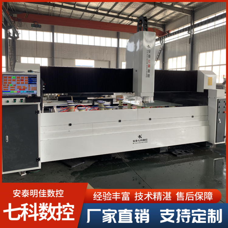
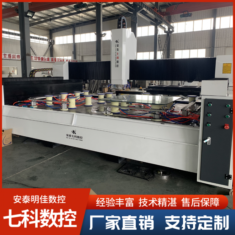
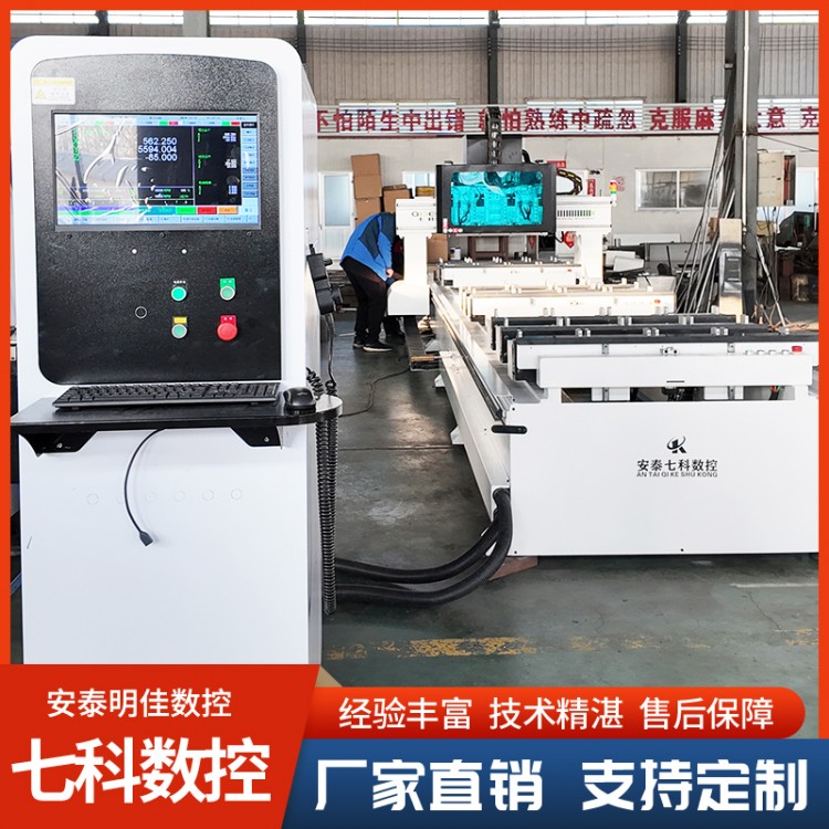
Numerical Control Cross-Cut Saws, Numerical Control Moldi...


Product Recommendation
When encountering a programming error in the CNC tenon and groove machine's control system, follow these steps to resolve the issue:
Incorrect Diagnosis
Check Alarm Messages: When a CNC system detects a program error, it typically emits an alarm signal and displays the corresponding alarm message on the screen. Carefully read the alarm messages, as they provide important clues about the type of error, such as "Program segment format error," "Undefined G-code," or "Tool radius compensation error," etc. This information helps to initially determine the approximate scope of the error.
Monitor Program Execution Status: Observe where the program stops executing or exhibits abnormal behavior. The program's execution can be tracked using the CNC system's program run monitoring feature to identify which line is causing issues, whether it's during tool movement commands, tool change commands, or other function commands.
2. Program Verification and Modification
Code Syntax Check
Format Check: Verify that the program format complies with the requirements of the numerical control system. For instance, numerical control programs generally adhere to strict formatting standards, including the format of program segments, instruction codes (such as G codes, M codes), coordinate values, feed rates, and more. Ensure that each program segment begins with the correct code, the writing of coordinate values follows the prescribed order of the coordinate axes (e.g., X, Y, Z sequence in rectangular coordinates), and the use of instruction codes aligns with the programming manual of the numerical control system.
Command Verification: Check the correct usage of commands such as G codes and M codes. Different CNC systems may have varying support and interpretations of commands. For instance, in some CNC systems, G00 is used for rapid positioning, while G01 is for linear interpolation; mixing them up can lead to programming errors. Additionally, verify that the commands are complete, such as when performing circular interpolation, where in addition to G codes, correct setting of the center coordinates or radius parameters is also required.
Parameter Inspection: Thoroughly review parameter settings within the program, such as feed rate (F-value), spindle speed (S-value), and tool compensation parameters. Ensure that these parameter values are within a reasonable range and match the actual machining requirements. For instance, if the set feed rate is too high, exceeding the machine tool's significant feed capacity, it may cause the motor to step out of sync or the machine tool to vibrate, affecting machining accuracy.
Logical Error Checking:
Tool Path Verification: Review the tool paths planned by the program to ensure they are reasonable. Confirm that the tool will not collide with the workpiece, fixture, or machine itself during movement. For instance, during mortise and tenon machining, the entry and exit paths of the tool should avoid interference with the edges of the workpiece. The tool path simulation feature of the CNC system can be used to visually inspect the tool paths and check for any irregularities.
Process Order Verification: Ensure the correct sequence of processing in the program. For instance, when performing multiple tenon and mortise operations, they should be carried out in a reasonable order to avoid missing or duplicating any tenon or mortise. Additionally, the processing sequence should also consider the stability of the workpiece clamping and processing efficiency, ensuring that initial processing does not affect subsequent operations.
3. Re-test and validate
Single-Step Execution Program: After modifying the program, use the CNC system's single-step execution feature to run the program step by step. This allows for a detailed observation of each step's execution to check for any remaining errors. If an issue is detected during single-step execution, the program can be promptly halted to make further modifications.
Air Running Test: Conducting an air running test, which involves operating the machine tool according to the program without actually cutting material. This helps to verify the correctness of the tool path, the movement of each axis, and the overall logic of the program. During the air running process, the focus is on whether the machine tool's movement aligns with expectations and if any alarm messages or abnormal behaviors occur.
Pilot Cutting Verification: After the no-load operation test is passed, proceed with the pilot cutting verification. Select an appropriate test material (such as scrap) and process it according to the modified program. During the cutting trial, closely monitor the processing quality, such as the dimensions, shape, and positional accuracy of the tenons and grooves. If the pilot cutting results are unsatisfactory, re-examine the program and make necessary modifications until satisfactory tenons and grooves are produced.


b2b.china9.net © Zhongshang 114 Hebei Network Technology Co., Ltd.Address: Room 6009, Oriental New World Center, No.118 East Zhongshan Road, Qiaoxi District, Shijiazhuang City, Hebei ProvincePlatform Service Hotline: 4006299930