Environmental equipment, instruments and meters, robots, ...

Feature Description
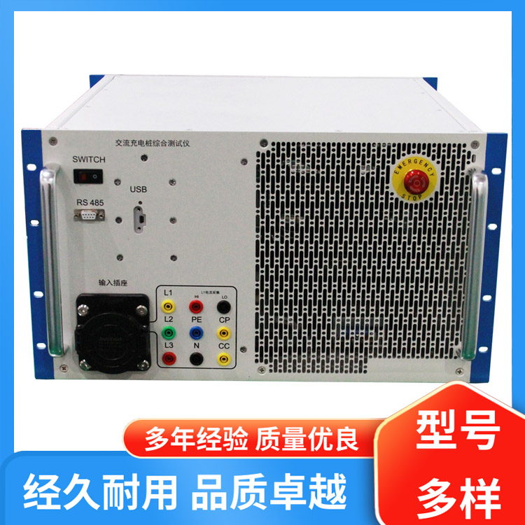
1. The output line is equipped with 10A and 20A circuit breakers in series for short-circuit protection. According to the special requirements of the customers, items 3, 4, 5, and 7 can be simultaneously closed and opened without interlock. Please note the usage requirements during operation.
Each time, only one power output group can operate.
2 Technical specifications: Items 1, 5, and 6 are not controlled by the contactor. As long as the main power switch is closed, it can output fixed values of three-phase AC380V, DC operating voltages of 24V, 36V, 110V, and 220V, as well as AC220V output (fixed value).
Three of the technical parameters are adjustable. Users simply need to turn on the main power and press the closing switch, then slowly increase until the desired voltage value is reached, and a three-phase AC 0-380V adjustable output can be achieved.
In the 4 technical parameters, there are 5 DC operating voltages, which include a fixed value and an adjustable value. The fixed value → Users can directly output the fixed values of 24V, 36V, 110V, and 220V by simply turning on the power switch on the rear panel.
Adjustable Voltage → After the power switch is turned on, the voltage gradually increases, allowing for a three-phase DC adjustable output ranging from 0 to 300V.
Closing switch → Start; Opening switch → Stop
Note: Please ensure that the options on both the front and back panels are consistent when performing any operation.
Operation Instructions
For example, using a single-phase AC voltage meter:
Plug the input power supply AC380V into the unit.
Connect the adjustable DC operating voltage power cord to the voltmeter.
Ensure and confirm that the wiring is correct and the main power switch is turned on.
Reset the pressure regulator to zero and press the "close" button.
Press the "Close" button on the panel for the DC operating voltage.
Gradually adjust the output control knob to increase the voltage to the required level, and observe the voltage gauge.
After the 7 tests are completed, first press the "break" button on the panel for the DC operating voltage.
Disengage the main circuit breaker on the panel, then, turn off the main power switch.
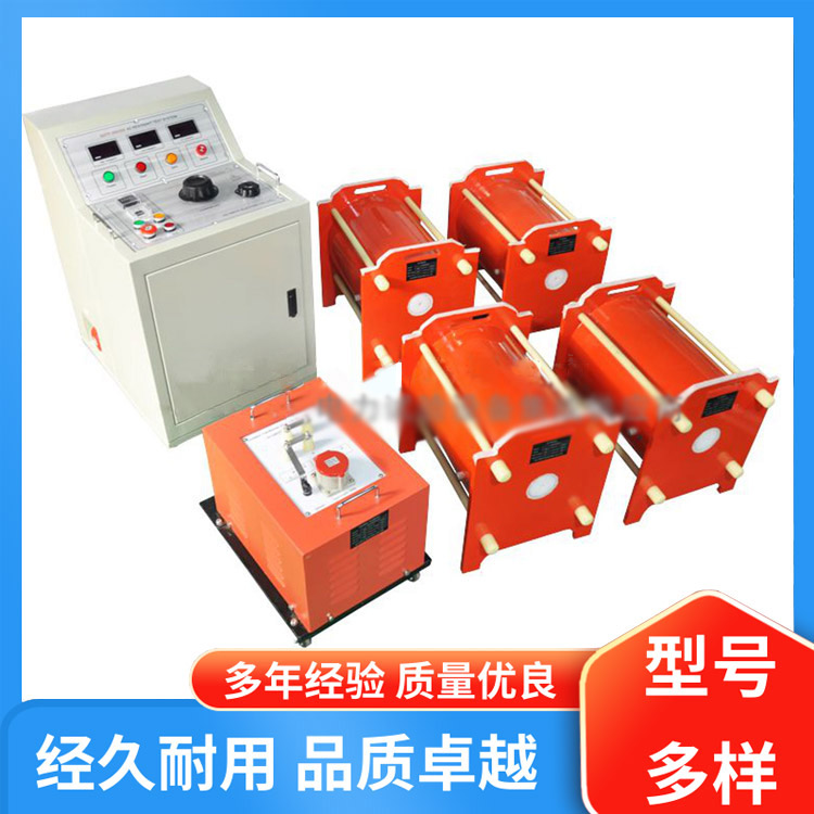
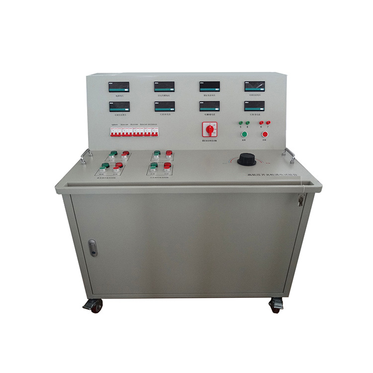
HZGK-II switchgear power supply, external power supply
This option is selected according to customer requirements.
This power supply is composed of a full-control three-phase rectifying module, phase-shifting trigger circuit, automatic regulation circuit, and absorption loop.
The transistor intelligent control module integrates complex automatic regulation circuits, thyristors, and trigger circuits into one unit. By adjusting the voltage of the control signal, it changes the conduction angle of the thyristor, thereby achieving the function of regulating and automatically controlling the power supply.
The trigger circuit system, thyristors, and heat-conducting substrates are mutually insulated and isolated. The dielectric strength exceeds 2500V, ensuring safe and convenient use. The three-phase rectifier module has no phase sequence restriction at the input. It is suitable for resistive and inductive loads.
User Instructions:
Connect to a three-phase four-wire AC 380V
Connect the DC voltage control output to the load.
Turn the output adjustment knob counterclockwise to the zero position.
Ensure all wiring is checked and confirmed correct.
Power switch turned on and off
Gently adjust the output potentiometer to increase the voltage to an appropriate level.
After the 7 tests are completed, first turn the output adjustment knob counterclockwise to the zero position, then turn off the power switch, and only after the discharge is complete can you begin to unwind the wires.


b2b.china9.net © Zhongshang 114 Hebei Network Technology Co., Ltd.Address: Room 6009, Oriental New World Center, No.118 East Zhongshan Road, Qiaoxi District, Shijiazhuang City, Hebei ProvincePlatform Service Hotline: 4006299930