Environmental equipment, instruments and meters, robots, ...

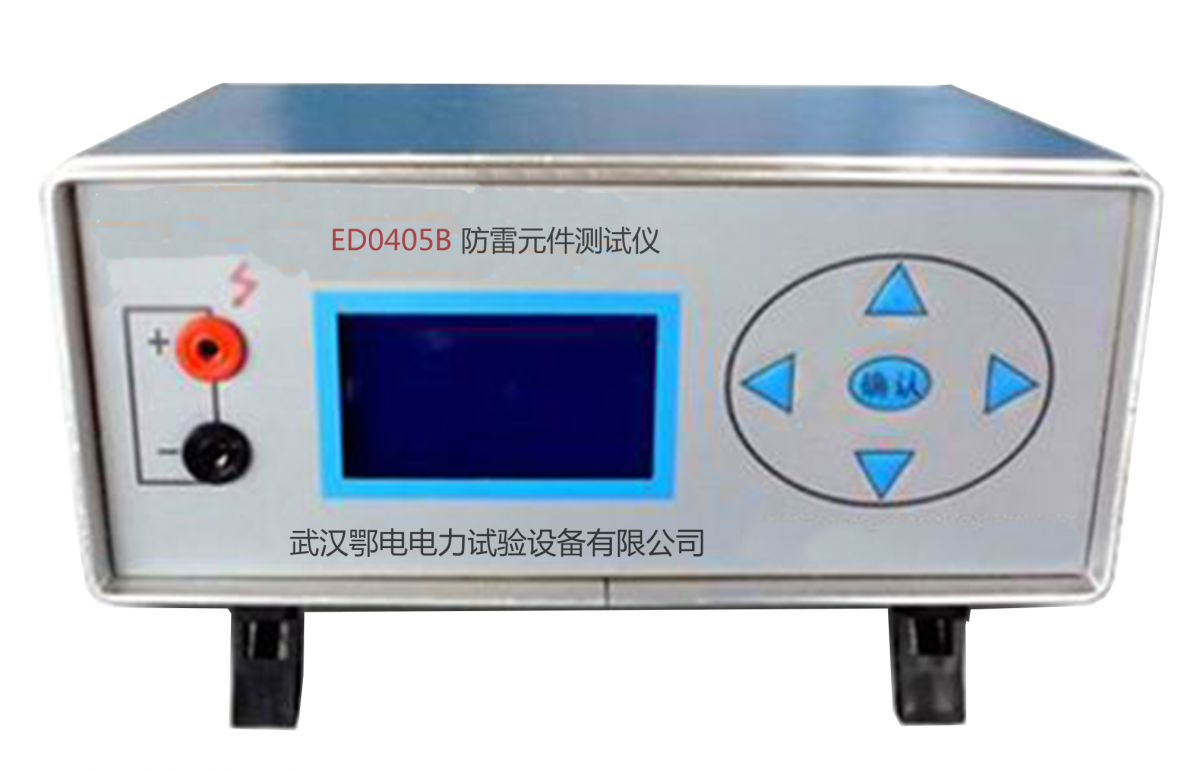
Lightning Protection Component Tester Performance Features
The Lightning Protection Element Tester is suitable for measuring the DC parameters of overvoltage protection elements such as zinc oxide lightning arresters (voltage-sensitive resistors), metal ceramic two and three electrode discharge tubes, and vacuum lightning arresters. It can also serve as a voltage regulator and constant current power supply, and is applicable in other areas.
The lightning protection component tester features high-voltage short-circuit protection, overcurrent protection, high-voltage presetting, range adjustment, and has a high-voltage self-discharge time of less than 0.5 seconds.
Self-checking function.
The measurement data is displayed on a 3 1/2 LCD digital screen, offering high accuracy and reliability.
During measurement, the range can be pre-set, and an audible alert will be triggered if the range is exceeded during the process, suitable for component grouping and discrimination.
Continuous measurement allows for uninterrupted testing of batches of samples.
The panel features simple and user-friendly functionality.
Lightweight and easy to carry.
Power Supply
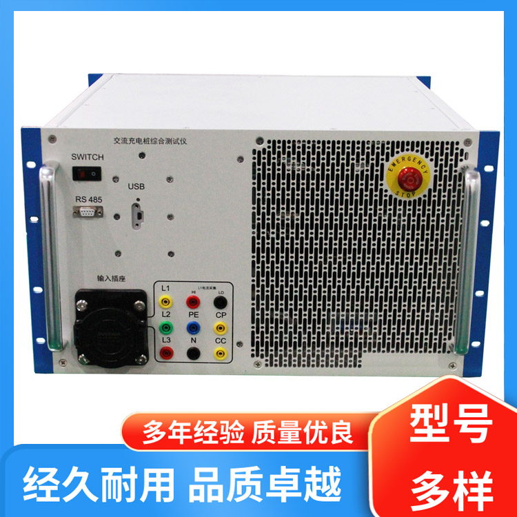
The rear panel features an external AC three-prong power socket, compatible with a 220V, 50Hz AC power grid. An AC power cord is included in the accessories.
The unit is equipped with an external DC power input socket of 12V/0.5A, with the core wire being the "+" pole. Users should pay attention to the polarity and wire diameter when providing their own power cord.
Prepared
1. Set all the self-locking push-button switches on the instrument panel to the highest position, and turn the adjustment knob counterclockwise to the end (small). Insert the test cables provided with the machine into the "+" and "-" test holes on the panel. Connect the external power source to the corresponding power socket (hole) on the back panel.
Turn on the power switch, and the instrument display should show "000."
3 Test
Tactile Resistor Testing
Range Setting
The "Sensitive Resistor/Discharge Tube" switch is set to the high position (Sensitive Resistor), the "Single/Continuous" switch is set to the high position (Single), and the "Voltage Pre-set" knob is turned clockwise to the end (maximum). Press the High Voltage button to activate high voltage, the high voltage indicator light illuminates, and the display shows the upper limit of the test voltage range. Adjust the "High Voltage Limit" knob to the desired value (upper limit of the test range).
Adjust the "Voltage Preset" knob to select the value you need (used to determine the lower limit of the test range).
At this point, the actual test range is 0V to the set upper limit of the range.
2 Measurement
a) The tested voltage-sensitive resistor is connected to the measuring line, then press the "High Voltage Start/Stop" button. The high voltage indicator light illuminates, and the display immediately shows the starting action voltage U1mA test value, with the unit "V" following the number. Press the "Test" button, and approximately 2 seconds later, it automatically switches to the leakage current I0.75U1mA test value, with the unit "μA". The green indicator light lights up in sync with the leakage current display and fades out after about 2 seconds. b) When the U1mA value of the tested voltage-sensitive resistor is below the voltage preset value, the display will drop to the U1mA value upon connection. Click the "Test" button to proceed with the next test step. If it exceeds the upper limit of the range, the U1mA period during the test process displays the preset range upper limit value. At this point, the test current is less than 1mA, and the displayed test data is invalid. To measure a new sample or to re-measure, simply click the "Test" button again.
c) For continuous measurements, set the "Single/Continuous" switch to the low position (continuous). (Select the continuous measurement mode before turning on high voltage by pressing the "Test" button once.)
Self-inspection and others
a) Check of the 1mA value for the photoresistor test
Select "Photoresistor" test, turn on high voltage, preset the voltage adjustment to above 10V, short-circuit the test holes at the "+" and "-" terminals, the display should show "000V", and while holding down the "Display Switch" button, it should display "1000μA".
b) Insulation Resistance Test Checking at 0.75U1mA Value
The test terminal is open. When the test button is clicked for testing, the display should show the upper range value. Holding down the "Display Conversion" button during the red light should display 0.75 times the upper range value.
During the testing process, hold down the "Display Conversion" button (do not release): During the U1mA measurement period, the displayed value is for Test Condition 1mA (1000μA); during the I0.75U1mA measurement period, the displayed value is for Test Condition 0.75U1mA.
Additionally, the voltage preset and range adjustment functions allow the device to function as a 1999V/1mA DC voltage regulator and a 1mA constant current source (the instrument maintains a constant output of 1mA when the load current reaches 1mA).
Using the "Display Conversion" key, load voltage and current (V/I characteristic) values can be measured in conjunction with the current (I) usage.
Discharge Tube Testing
Range Setting
"Sensitive Resistor/Discharge Tube" switch set to low position (Discharge Tube), set the range according to method 1.
2 Measuring
Connect the tested discharge tube to the test line.
If the green indicator light is on, it means the test item's ignition voltage value, Vsdc, is less than the "Voltage Preset" value (below the overrange lower limit), and the buzzer will emit an audible alert. At this point, the test item should be removed promptly; otherwise, it will be ignited repeatedly.
If the green indicator light is not illuminated, it indicates that the ignition voltage (Vsdc) of the item being tested is greater than the "Voltage Preset" value. Click the "Test Button" to proceed to the next step.
b) After clicking the "Test" button, the test voltage begins to rise from the voltage preset value at a rate of 100V/S until the green indicator light illuminates.
If the buzzer does not sound, the display will show the value within the measurement range.
If the buzzer sounds, the display will show the upper limit of the measurement range. At this point, it indicates that the ignition voltage Vsdc of the item being tested is greater than the upper limit of the measurement range (over-range limit) but no ignition has occurred.
The green indicator light illuminates and the corresponding displayed value (with an audible beep when out of range) will automatically disappear after about 2 seconds, followed by returning to the preset state.
Remove tested discharge tubes during the green indicator light, reconnect after the preset voltage is restored for the next test with the 待测 discharge tube.
c) Continuous Measurement
Set the "Single/Continuous" switch to the low position (Continuous position) for continuous measurements.
The test is complete. Click the "High Voltage" button to shut off the test voltage and turn off the power by placing the back panel power switch in the "OFF" position. Remove the power cord when using an external DC 12V power supply.


b2b.china9.net © Zhongshang 114 Hebei Network Technology Co., Ltd.Address: Room 6009, Oriental New World Center, No.118 East Zhongshan Road, Qiaoxi District, Shijiazhuang City, Hebei ProvincePlatform Service Hotline: 4006299930