Environmental equipment, instruments and meters, robots, ...

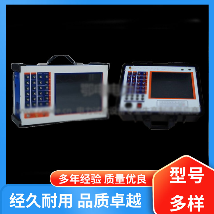
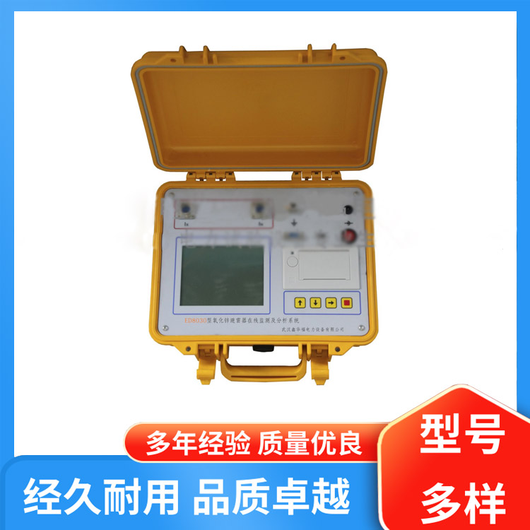
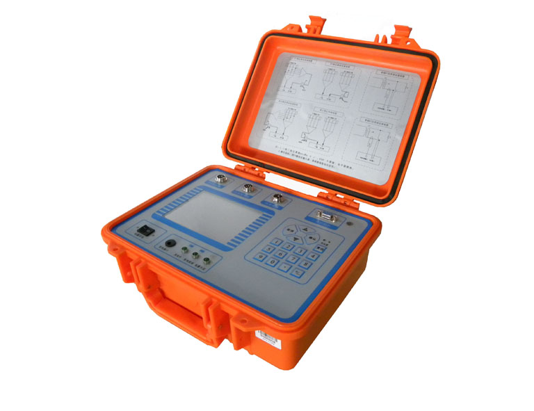
Introduction to the Dual Load Test Instrument
The overall error of an electrical energy metering device is the comprehensive error of electrical energy metering, which is composed of errors from the electrical energy meter, composite errors from voltage transformers, composite errors from current transformers, and metering errors caused by voltage drop in the secondary conductors of the voltage transformer. This can be expressed by the following formula:
ε=εw+εTA+εTV+εr
εw – Percentage Error of the Energy Meter
ETA — Current Transformer Synthesized Error %
εTV — Voltage Transformer Synthetic Error %
εr — Percentage measurement error caused by secondary conductor voltage drop of transformer voltage ratio relay
In power plants and substation electrical energy measurement loops, the outdoor voltage transformers are located at a considerable distance from the electrical meters installed on the control room distribution board, typically ranging from 200 to 400 meters. The entire loop includes wiring terminals, switches, fuses, and conductors, inevitably introducing contact resistance, conductor resistance, and distributed parameters, resulting in a certain loop impedance. This causes a voltage drop across the secondary circuit between the voltage transformer and the electrical meter. The voltage drop in the voltage transformer's secondary circuit includes the total sum of voltage drops from cables, terminal contact resistance, fuse wires, intermediate relay contacts, and air switches. The error caused by the voltage drop in the secondary voltage of the voltage transformer refers to the percentage difference in the amplitude of the voltage between the secondary terminal and the load terminal, relative to the actual secondary voltage, as well as the total phase difference between the two voltages.
The State Grid Corporation's Production and Operation Department's new "On-site Inspection Operation Manual for Electric Energy Measuring Devices" explicitly stipulates the measurement of the actual secondary load of current transformers and voltage transformers.
Secondary Actual Load of Voltage Transformer:
In actual operation, the total admittance is composed of the capacitance between the measuring instruments connected to the secondary side and the secondary cables, as well as between the cables and the ground wire.
Secondary Actual Load of Current Transformers:
In actual operation, the total effective impedance consists of the impedance of the measuring instruments connected to the secondary, the secondary cable, and the contact resistance.
The dual load tester features the following functions:
⑴. Achieves full automation in measurement.
Utilizing engineering plastic enclosures, the product offers durability and effectively ensures the safety of test personnel and the system.
The instrument features an automatic range switching function, ensuring testing accuracy.
The combination of electronic principle circuitry with DSP technology ensures excellent test stability and strong anti-interference capability.
Upon completion of the measurement, the system automatically calculates various parameters for customer analysis and testing convenience.
⑥. Featuring large-screen Chinese LCD display, all operations are prompted through Chinese menu options; data supports power-off storage and browsing capabilities, and can be connected to a computer for data transfer.
⑺. Equipped with a high-capacity 7.2V11Ah lithium battery, it supplies power without affecting the test circuit, preventing any system protection scenarios. Additionally, it can be used in situations where there is no power supply on-site.
⑻. The secondary load test utilizes a clamp-on ammeter to sample current without the need to disconnect the secondary circuit. This allows for uninterrupted online measurement. Automatic range switching: During the measurement process, the range can be switched to different positions based on the value of the test object, ensuring measurement accuracy and display precision.
Work hours can extend up to 24 hours (long), and can be measured while charging.
⑽. Equipped with a compact charger, convenient for measurement, and capable of being connected to an external charger for measurement when the battery is low.
The instrument is compact and lightweight.
It can store 480 sets of measurement data and retains the information for up to ten years after power interruption.
⒀. Large screen with Chinese interface, featuring RS-232 communication interface
Key Technical Indicators
Environmental Conditions
——Temperature: -5°C to 40°C
Relative humidity: <95% (at 25°C)
—— Altitude: <2500m
External Interference: No severe vibrations, no severe electromagnetic fields
2. PT Secondary Load Test Instrument Main Technical Specifications
⊙ Measurement Accuracy of Admittance
X = (X × 2% + Y × 2%) squared
Y = (Y × 2% + X × 2% × 34.38) squared
Two Words — Quantitative Error of the Instrument
Voltage Gauge: 0.5%
○ Resistance Measurement Range: 0.1Ω - 50.0Ω
⊙ Accuracy of Impedance Measurement:
X = (X * 2% + Y * 2%) squared
Y = (Y × 2% + X × 2% × 34.38) squared
Two Words – Quantitative Error of the Instrument
Ammeter Head: 1%
3. CT Secondary Load Test Instrument Key Technical Specifications
Impedance measurement range: 0.1Ω - 50.0Ω
—— Impedance Measurement Accuracy:
X = (2% * X + 2% * Y) squared
Y = (2% × X + 2% × Y) squared
Two Words – Quantitative Error of the Instrument
Ammeter Head: 1%


b2b.china9.net © Zhongshang 114 Hebei Network Technology Co., Ltd.Address: Room 6009, Oriental New World Center, No.118 East Zhongshan Road, Qiaoxi District, Shijiazhuang City, Hebei ProvincePlatform Service Hotline: 4006299930